A cable manhole cover transporter
A cable manhole cover and truck technology, which is applied to motor vehicles, trolleys, trolley accessories, etc., can solve the problem of inconvenient transportation of cover plates, and achieve the effects of convenient and labor-saving transportation, simple transportation and high efficiency.
- Summary
- Abstract
- Description
- Claims
- Application Information
AI Technical Summary
Problems solved by technology
Method used
Image

Examples
Embodiment 1
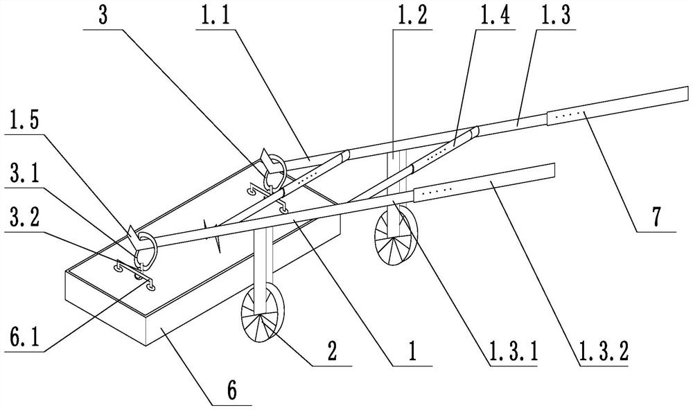
[0027] Such as figure 1 As shown, a cable well cover truck includes a support frame 1, wheels 2 and gibs 3, the support frame 1 includes a lifting rod 1.1, a wheel frame 1.2 and a handrail 1.3, and the lifting rod 1.1 and the handrail 1.3 are respectively arranged on the wheel On the opposite sides of the frame 1.2, the length of the lifting rod is less than the length of the handrail rod, the wheel 2 is rotationally connected with the wheel frame 1.2, and the hook head 3 is arranged on the end of the lifting rod 1.1 away from the wheel frame 1.2; the hand lever includes a connecting rod 1.3.1 and the first telescopic rod 1.3.2, the connecting rod 1.3.1 is fixed to the wheel frame 1.2, the first telescopic rod 1.3.2 is telescopically connected to the connecting rod 1.3.1, and the first telescopic rod 1.3.2 is sleeved on the connecting rod 1.3 .1 on the outer side, and the connecting rod 1.3.1 is provided with a locking structure 7, which is used to lock the first telescopic ro...
Embodiment 2
[0030] Such as figure 1As shown, on the basis of Example 1, the hook head 3 includes a suspension ring 3.1 and a suspension hook 3.2, the suspension hook 3.2 is fixed to the suspension ring 3.1, the suspension ring 3.1 is set on the lifting rod 1.1, and the lifting rod 1.1 is away from the wheel frame 1.2. One end is provided with a limit hook 1.5 for limiting the suspension ring 3.1, and the suspension ring 3.1 is a flexible structure. The structure can conveniently hook the hook 3.2 on the hook 6.1 on the well cover plate 6, and connect with the lifting rod 1.1 through the lifting ring 3.1. The limit hook 1.5 can prevent the lifting ring 3.1 from breaking away from the lifting rod 1.1 during the transportation process. The lifting ring 3.1 can be deformed, which is convenient for tightening the lifting rod 1.1, and can also improve the allowable tolerance range between the spacing of the lifting rod 1.1 and the spacing of the two hooks 6.1 on the well cover plate 6 through t...
Embodiment 3
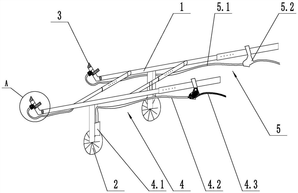
[0032] Such as figure 2 As shown, on the basis of Embodiment 1, a brake structure 4 is also included. The brake structure 4 includes a brake structure 4.1, a brake rope 4.2 and a brake handle 4.3. The brake structure 4 is arranged at a position close to the wheel 2 and connected to the wheel frame 1.2 is fixed, the brake handle 4.3 is fixed with the handrail bar 1.3, and the brake rope 4.2 is connected with the brake structure 4.1 and the brake handle 4.3. The braking structure 4 can brake the transport vehicle to facilitate transport. The brake structure 4.1, the brake rope 4.2 and the brake handle 4.3 can adopt parts commonly used on bicycles and electric bicycles, as long as they can realize the braking function.
PUM
 Abstract
Description
Claims
Application Information
 - R&D
- Intellectual Property
- Life Sciences
- Materials
- Tech Scout
- Unparalleled Data Quality
- Higher Quality Content
- 60% Fewer Hallucinations
Browse by: Latest US Patents, China's latest patents, Technical Efficacy Thesaurus, Application Domain, Technology Topic, Popular Technical Reports.
© 2025 PatSnap. All rights reserved.Legal|Privacy policy|Modern Slavery Act Transparency Statement|Sitemap|About US| Contact US: help@patsnap.com