Multi-station integrated hydraulic trimming die machine
An integrated, multi-station technology, applied in the direction of manufacturing tools, metal processing, metal processing equipment, etc., can solve problems such as low efficiency, waste of production time, increase of production cost, etc., to reduce pressure, reduce scrap rate, and reduce production cost effect
- Summary
- Abstract
- Description
- Claims
- Application Information
AI Technical Summary
Problems solved by technology
Method used
Image

Examples
Embodiment 1
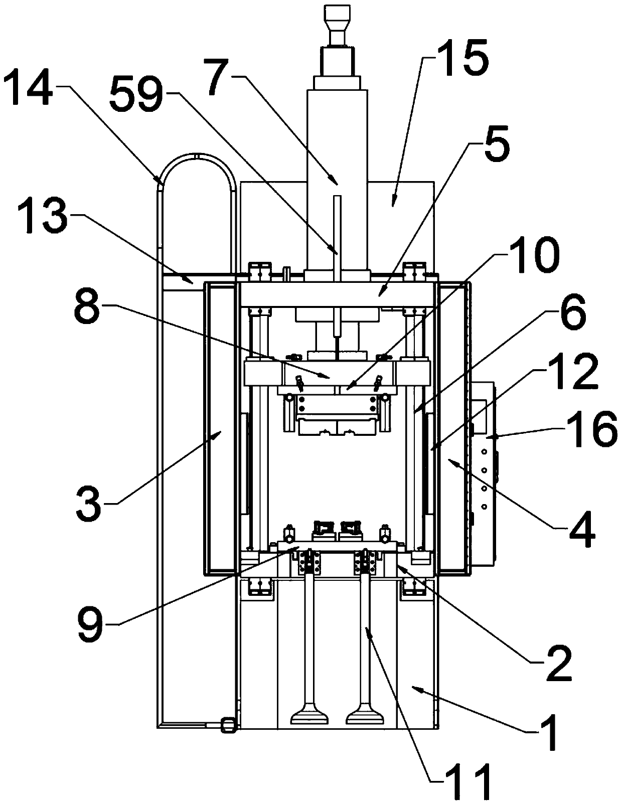
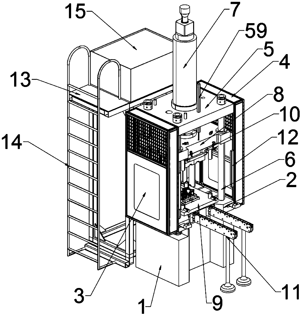
[0052] The present invention provides a multi-station integrated hydraulic trimming die machine, which is characterized by comprising a base 1, a machine table 2, a left mounting shell 3, a right mounting shell 4, a top mounting plate 5, a sliding rod 6, and a two-stage hydraulic cylinder 7. Machine slide 8, mold assembly, mold installation auxiliary slide 11, grating sensor 12, displacement sensor 59, mounting frame 13, ladder 14, hydraulic oil tank 15 and electric control cabinet 16; an organic platform 2 is installed above the base 1 , The front of the machine 2 is equipped with a mold installation auxiliary slide rail 11, the left side of the machine 2 is provided with a left installation shell 3, the right side of the machine 2 is provided with a right installation shell 4, and the top of the left installation shell 3 and the right installation shell 4 are provided The top mounting plate 5, the top mounting plate 5 is equipped with a two-stage hydraulic cylinder 7 on the to...
Embodiment 2
[0062] The present invention provides a multi-station integrated hydraulic trimming die machine, which is characterized by comprising a base 1, a machine table 2, a left mounting shell 3, a right mounting shell 4, a top mounting plate 5, a sliding rod 6, and a two-stage hydraulic cylinder 7. Machine slide 8, mold assembly, mold installation auxiliary slide 11, grating sensor 12, displacement sensor 59, mounting frame 13, ladder 14, hydraulic oil tank 15 and electric control cabinet 16; an organic platform 2 is installed above the base 1 , The front of the machine 2 is equipped with a mold installation auxiliary slide rail 11, the left side of the machine 2 is provided with a left installation shell 3, the right side of the machine 2 is provided with a right installation shell 4, and the top of the left installation shell 3 and the right installation shell 4 are provided The top mounting plate 5, the top mounting plate 5 is equipped with a two-stage hydraulic cylinder 7 on the to...
Embodiment 3
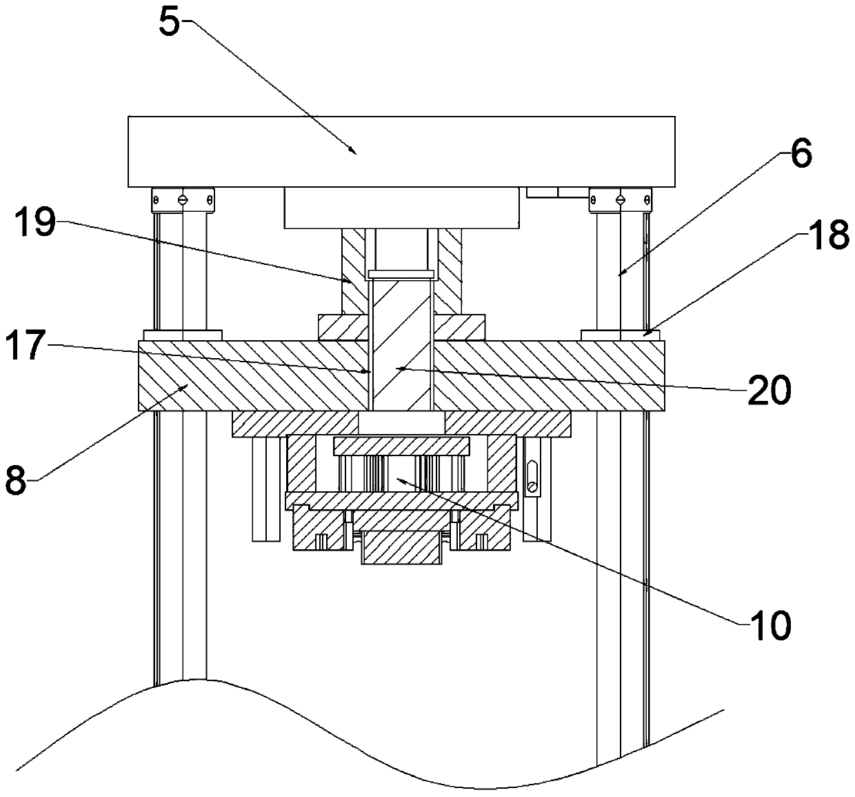
[0071] When the mold has a top-up and top-out structure, the upper mold 10 and the lower mold 9 are installed on the machine slide 8 and the machine table 2 respectively, and the workpiece A57 is placed on the lower mold positioning block 23 of the lower mold 9. Then the two-stage hydraulic cylinder 7 is started. The two-stage hydraulic cylinder 7 pushes out the first-level hydraulic rod 19 under the control of the control system of the electric control cabinet 16, and the first-level hydraulic rod 19 pushes the machine slide 8 to move down along the sliding rod 6. At the same time, the upper mold 10 moves downward under the drive of the machine slide 8 until the tool block 27 contacts the workpiece A57. The upper mold 10 continues to press down so that the tool block 27 cuts the burrs of the workpiece A57, and the insert 28 is folded The linear cutting edge 37 cuts the riser for the first time to reduce the thickness of the riser, and the insert 28 continues to drop. The V-shap...
PUM
 Abstract
Description
Claims
Application Information
 - R&D
- Intellectual Property
- Life Sciences
- Materials
- Tech Scout
- Unparalleled Data Quality
- Higher Quality Content
- 60% Fewer Hallucinations
Browse by: Latest US Patents, China's latest patents, Technical Efficacy Thesaurus, Application Domain, Technology Topic, Popular Technical Reports.
© 2025 PatSnap. All rights reserved.Legal|Privacy policy|Modern Slavery Act Transparency Statement|Sitemap|About US| Contact US: help@patsnap.com