Power takeoff and power taking method
A power take-off and power technology, applied in the field of vehicle accessories, can solve the problems of increasing the difficulty, difficulty and complexity of power take-off, affecting the power take-off efficiency, etc., to achieve the effect of improving the experience, reducing the difficulty of taking power, and being convenient to use.
- Summary
- Abstract
- Description
- Claims
- Application Information
AI Technical Summary
Problems solved by technology
Method used
Image

Examples
no. 1 example
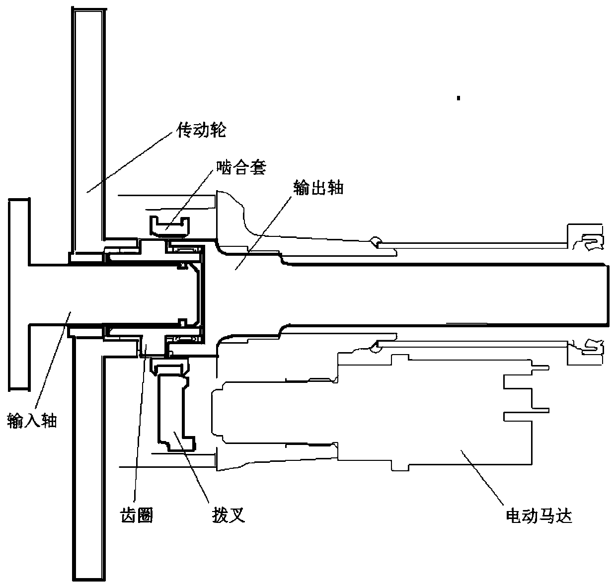
[0044] see figure 1 , which is a cross-sectional view of a power take-off provided in an embodiment of the present application.
[0045] Such as figure 1 As shown, the power take-off provided by the embodiment of the present application includes: a transmission wheel, an input shaft, a ring gear, an output shaft, an engaging sleeve, a shift fork and a power source.
[0046]In this embodiment, the power take-off can be arranged between the vehicle gearbox and the vehicle transmission shaft. The input shaft of the power take-off is used to connect the output shaft of the vehicle gearbox; the output shaft of the power take-off is used to connect the vehicle transmission shaft. There is an assembly relationship between the ring gear and the input shaft. After the ring gear and the input shaft are assembled and the power take-off works normally, there is no mutual movement between the ring gear and the input shaft.
[0047] In this embodiment, the power source is capable of rec...
no. 2 example
[0058] see Figure 4 , which is a cross-sectional view of the power take-off provided in the embodiment of the present application.
[0059] Such as Figure 4 As shown, on the basis of the transmission wheel, input shaft, ring gear, output shaft, meshing sleeve, shift fork and power source provided by the power take-off provided in the previous embodiment, the power take-off provided in this embodiment further includes: Working status prompt device. The working state prompting device is connected with a power source.
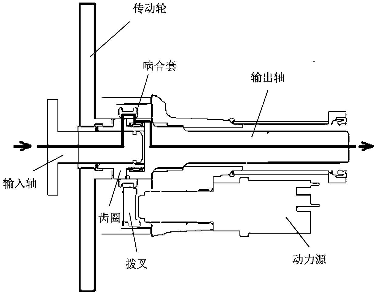
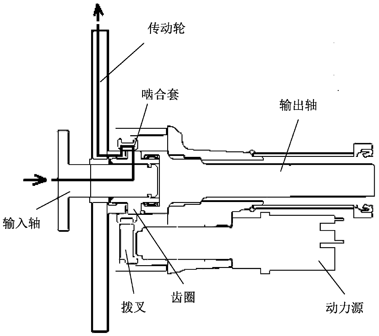
[0060] Under the action of the first input signal, the movable part of the power source pushes the shift fork to move to the first position, the meshing sleeve is connected with the transmission wheel and the ring gear through the shift fork, and the power of the vehicle gearbox passes through the input shaft, the ring gear in turn , the meshing sleeve and the drive wheel are transmitted to the engineering power take-off equipment outside the vehicle. When t...
no. 3 example
[0072] see Figure 5 , which is a flow chart of a force taking method provided in the embodiment of the present application. This method is applied to the power take-off provided in the foregoing embodiments. That is, the power take-off at least includes: a transmission wheel, an input shaft, a ring gear, an output shaft, an engaging sleeve, a shift fork and a power source, wherein the position of the engaging sleeve changes with the position of the shift fork. The power take-off is arranged between the vehicle gearbox and the vehicle transmission shaft.
[0073] Such as Figure 5 As shown, the force taking method provided in this embodiment includes:
[0074]Step 501: Receive a first input signal, under the action of the first input signal, the movable part of the power source pushes the shift fork to move to the first position, and the ring gear is connected with the transmission through the engagement sleeve The wheel realizes the indirect connection.
[0075] Step 502...
PUM
 Abstract
Description
Claims
Application Information
 - R&D
- Intellectual Property
- Life Sciences
- Materials
- Tech Scout
- Unparalleled Data Quality
- Higher Quality Content
- 60% Fewer Hallucinations
Browse by: Latest US Patents, China's latest patents, Technical Efficacy Thesaurus, Application Domain, Technology Topic, Popular Technical Reports.
© 2025 PatSnap. All rights reserved.Legal|Privacy policy|Modern Slavery Act Transparency Statement|Sitemap|About US| Contact US: help@patsnap.com