Examination table for psychiatry department

A psychiatric and diagnostic technology, applied in the medical field, can solve problems such as lack of protective measures, loose masks, falling off, etc., and achieve the effect of reducing the risk of disease transmission to doctors and avoiding discomfort

Inactive Publication Date: 2020-09-01
李红梅
1 Cites 2 Cited by

AI-Extracted Technical Summary

Problems solved by technology

[0003] The existing patent No. CN106263594B proposes a table for doctors with a heating function, which has functions such as foot massage, but the psychiatrist needs to talk with the patient during the consultation, and during the period of high incidence of infectious diseases , even if wearing a mask, it is easy for the mask to loosen and fall off when talking, causing the patient's saliva to easily float in the air. If the patient carries the virus in h...

Method used

The inside of baffle plate 4 is hollowed out state, and the right side inner wall of baffle plate 4 is fixedly connected with three groups of loudspeaker tubes 9, and loudspeaker tube 9 is a hollow circular frustum and runs through the right side of baffle plate 4, and loudspeaker tube One side with 9 diameters is big to the left, and the quantity of every group of loudspeaker tubes 9 is seven and three groups of loudspeaker tubes 9 are circularly distributed, through the setting of the loudspeaker tubes 9, ...

Abstract

The invention relates to the technical field of medical treatment. The invention discloses an examination table for the psychiatry department. The examination table comprises a table plate and table legs, and the two table legs are fixedly connected to the front bottom face and the rear bottom face of the table board respectively. A sleeve is fixedly connected to the middle of the bottom surface of the table plate; the position, corresponding to the sleeve, of the top face of the table plate is hollowed out; a groove is formed in the inner wall of the hollowed-out portion of the left side of the table board, and a rotating rod B is sleeved with the groove. The right end of the rotating rod B is fixedly connected with a baffle; a camera is fixedly mounted at the top end of the right side ofthe baffle; a control panel is fixedly mounted on the top surface of the left side of the table plate; a display screen is mounted on the control panel; the camera is electrically connected with thecontrol panel; through the arrangement of the baffle, the baffle can be switched between the containing state and the standing state, when a patient suffers from infectious diseases, the patient can be separated from a doctor, and therefore, the risk that the disease is infected to the doctor is reduced, the sight of the patient can be blocked when the patient suffering from mental diseases such as autism is examined, and discomfort caused by the fact that the patient makes contact with strangers is avoided.

Application Domain

SurgeryVaccination/ovulation diagnostics +6

Technology Topic

Mental diseaseEngineering +8

Image

  • Examination table for psychiatry department
  • Examination table for psychiatry department
  • Examination table for psychiatry department

Examples

  • Experimental program(3)

Example Embodiment

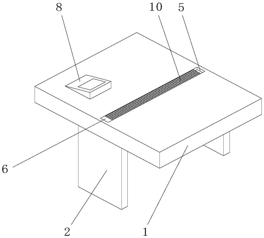
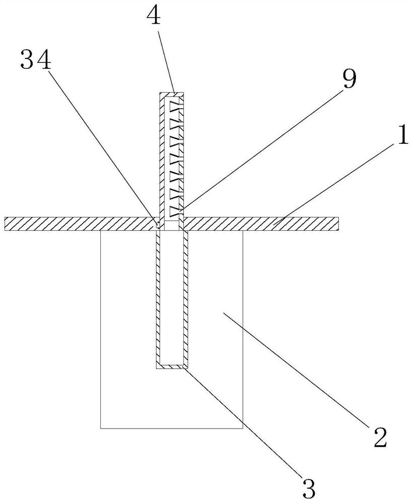
[0043] Example 1: Please refer to Figure 1-4 , The present invention proposes a psychiatric examination table, including a table 1 and a table leg 2, the number of the table leg 2 is two and respectively fixedly connected to the front and rear bottom surface of the table board 1, and the middle of the bottom surface of the table board 1 is fixedly connected There is a sleeve 3, the shape of the sleeve 3 is semi-cylinder and the top surface is hollowed out. The top surface of the table top 1 corresponds to the position of the sleeve 3 in a hollowed state. The inner wall of the left hollow on the table top 1 is provided with a groove and groove A rotating rod B34 is sleeved inside, the right end of the rotating rod B34 is fixedly connected with a baffle 4, the shape of the baffle 4 is a semi-cylinder and the size is matched with the inner wall of the sleeve 3, and the back bottom end of the baffle 4 is fixedly connected There is a plug-in board 6, and the top surface of the table board 1 is provided with slots 5 on the front and rear sides of the baffle 4. The shape and size of the slot 5 are adapted to the plug-in board 6, and the top of the right side of the baffle 4 is fixedly installed There is a camera 7, a control panel 8 is fixedly installed on the top surface of the left side of the table board 1, and a display screen is installed on the control panel 8. The camera 7 is electrically connected to the control panel 8. The baffle 4 is first pushed to house it in the sleeve Inside 3, the bottom surface of the baffle 4 and the top surface of the table 1 form a complete desktop. When a patient suffering from an infectious disease appears, push the baffle 4 out of the sleeve 3 to make the baffle 4 stand on On the sleeve 3, the patient is separated from the doctor, and then the camera 7 photographs the patient and transmits it to the control panel 8. The doctor observes the patient through the control panel 8, and is connected to the socket 6 through the slot 5 , It has a fixed effect on the upright and housed baffle 4. Through the setting of the baffle 4, the baffle 4 can switch between the accommodating and standing states, which can separate the patient from the doctor when the patient has an infectious disease. It can reduce the risk of disease spreading to doctors, and patients with mental illnesses such as autism during the examination can obstruct the patient’s sight and avoid the discomfort caused by contact with strangers.
[0044] The inside of the baffle 4 is in a hollow state. The right inner wall of the baffle 4 is fixedly connected with three sets of loudspeaker tubes 9. The loudspeaker tube 9 is a hollow truncated cone and penetrates the right side of the baffle 4. The loudspeaker tube 9 has a large diameter. The side facing left, the number of loudspeaker tubes 9 in each group is seven and the three sets of loudspeaker tubes 9 are distributed in a circular shape. Through the arrangement of the loudspeaker tubes 9, the loudspeaker tube 9 in the shape of a horn is used to realize the sound wave The sound reinforcement effect allows the sound to pass directly through the right side wall of the baffle 4, thereby helping the doctor to accurately hear the patient’s voice, which is conducive to the diagnosis work when the doctor and the patient are separated by the baffle 4. The setting of multiple sets of loudspeaker tubes 9 increases the range and effect of loudspeaker tubes 9.

Example Embodiment

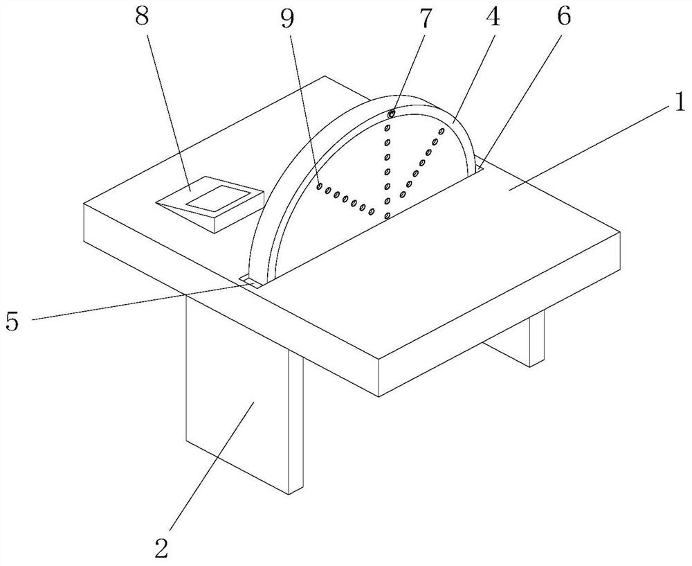
[0045] Example 2: Please refer to Figure 5-9 On the basis of the first embodiment, the bottom surface of the baffle 4 is in a hollow state, the bottom surface of the sleeve 3 is fixedly connected with a connecting column 11, the top surface of the connecting column 11 is hollowed out and communicates with the inside of the sleeve 3, and the two connecting columns 11 The sides are fixedly connected and communicated with a connecting pipe 12, and the ends of the two connecting pipes 12 away from the connecting column 11 are fixedly connected with a gas barrier 14. The bottom surface of the gas barrier 14 is provided with a circular truncated hole, and the side of the circular truncated hole with a smaller diameter is upward , The inner wall of the air barrier 14 is fixedly connected with a spring A16, the top of the spring A16 is fixedly connected with a round plate 15 which is attached to the inner wall of the air barrier 14, and the bottom surfaces of the two air barriers 14 are fixedly connected with a circle Cylinder 13, the cylinder 13 is a hollow cylinder and is connected with two gas barriers 14. The two sides of the bottom surface of the cylinder 13 are also fixedly connected and communicated with the gas barriers 14, and the inner wall of the cylinder 13 is sleeved with a piston A17, the piston A17 is made of metal, the middle outer wall of the cylinder 13 is sleeved with a slip ring 18, the slip ring 18 is made of a strong magnet, and the piston A17 is attracted by the slip ring 18.
[0046] A rotating motor 22 is fixedly installed under the table board 1, and the rotating motor 22 is electrically connected to the control panel 8. The drive shaft of the rotating motor 22 is fixedly connected with a turntable 23. The outer edge of the front of the turntable 23 is fixedly connected with a round rod 24. A connecting rod 25 is sleeved on the outer wall of 24. The connecting rod 25 is rectangular and has an elliptical hole on the front. The top surface of the connecting rod 25 is fixedly connected with a splint 19, which is a C-shaped body, and the inner wall of the splint 19 is The ring 18 is sleeved, and when the air barrier 14 is in an upright state, the rotating motor 22 is controlled by the control panel 8 to start, and the drive shaft of the rotating motor 22 drives the turntable 23 to rotate. The turntable 23 passes through the sleeve of the round rod 24 and the connecting rod 25. The connection drives the splint 19 to rotate. The splint 19 keeps the inner wall upward through the sleeve connection with the slip ring 18 and drives the slip ring 18 to slide left and right. When the slip ring 18 slides left and right, the magnetic force drives the piston A17 to slide left and right, and the piston A17 will squeeze when sliding left and right. Press the air in the cylinder 13 on one side and generate negative pressure in the cylinder 13 on the other side. The compressed air pushes the upper circular plate 15 to close the air barrier 14 and pushes the lower circular plate 15 to expand the air barrier 14. Thereby the air in the cylinder 13 is discharged, the negative pressure pushes the lower round plate 15 to close the air barrier 14 and pulls the upper round plate 15 to expand the air barrier 14, and then the negative pressure draws the baffle through the connecting pipe 12 and the sleeve 3. 4, and then the baffle 4 draws outside air through the loudspeaker tube 9. Through the setting of the cylinder 13, the outside air is drawn through the loudspeaker tube 9 after the rotating motor 22 is started, and the air corresponding to the patient side is drawn in. Prevent saliva and other infectious sources from floating in the air, further reducing the risk of disease transmission, and through the effect of multiple sets of loudspeakers 9, increase the range of air inhalation, and further prevent saliva and other infectious sources from floating in the air through the cylinder The setting of 13 uses the left and right shaking of the piston A17 to achieve a state of uninterrupted air extraction, ensuring the effect of extracting infectious sources such as patient saliva, so as to maximize the risk of virus floating in the air. Through the setting of cylinder 13, Utilizing the air extraction effect to accelerate the circulation of air near the loudspeaker tube 9 has the effect of generating wind current near the patient, reducing the patient's body temperature raised due to tension, and using wind current to blow the patient’s cheeks to encourage the patient to calm down, which is beneficial to improve the patient’s health Comfort.
[0047] The bottom surface of the baffle 4 is fixedly connected to the bottom plate 10, and the top surface of the bottom plate 10 is laid with holes. The bottom plate 10 is provided to fill the hollow of the bottom surface when the baffle 4 is contained in the sleeve 3, ensuring that the baffle 4 and the sleeve When the barrel 3 is ventilated, the problem of sundries falling into the baffle 4 is avoided, and the normal use of the table 1 after the baffle 4 is contained in the sleeve 3 is ensured.
[0048] The inner walls of the two air barriers 14 located below are provided with threaded grooves and are threadedly connected with a filter barrel 20. The inner wall of the filter barrel 20 is fixedly connected with three sets of filter plates 21. The front of the filter barrel 20 is provided with holes under the filter plate 21. The user can communicate with the hole on the front of the filter barrel 20 through a pipe, and then connect the pipe to an air purification device. The air discharged from the cylinder 13 will be filtered by the filter plate 21 to filter out impurities and saliva in the air. The filtered air is discharged through the filter bucket 20. Through the setting of the filter bucket 20, the air near the patient discharged from the cylinder 13 is filtered, and the filtered air is discharged in a concentrated manner to prevent the air from floating with virus-containing saliva when the cylinder 13 discharges the air. After use, the doctor removes the filter barrel 20 and then takes out the filter plate 21 to detect the impurities and saliva filtered by the filter plate 21 to detect whether the patient carries the virus.
[0049] A movable cylinder 26 is fixedly connected to the back side of the sleeve 3, and the movable cylinder 26 is a rectangular body with a hollow top surface and a front surface, and the movable cylinder 26 communicates with the inside of the sleeve 3, and the front inner wall of the movable cylinder 26 is fixedly connected with a cylinder plate 27 , The front of the cylinder plate 27 is flush with the inner wall of the back side of the sleeve 3, the bottom end of the movable cylinder 26 is provided with a hole and a rotating rod A28 is sleeved in the hole, and the end of the rotating rod A28 located in the movable cylinder 26 is fixedly connected with the rotating Column 29, the outer wall of the rotating column 29 is fixedly connected with twenty fan blades 30 at equal intervals, and the bottom end of the back side of the cylinder plate 27 is fixedly connected with an air duct 31, which is a hollow J-shaped body and is connected to the sleeve 3. The air duct 31 is located inside the movable cylinder 26. The end of the air duct 31 away from the cylinder plate 27 corresponds to the fan blade 30. The back side of the movable cylinder 26 is provided with a hole above the back side of the rotating column 29, and the bottom surface of the table 1 corresponds to the movable cylinder. There is a slot at the position 26 and the rotating rod B34 is located in the slot. The left end of the rotating rod B34 and the right side of the rotating column 29 are fixedly connected with a pulley 32. The two pulleys 32 are connected by a belt 33, and the baffle 4 is housed in the sleeve. When the cylinder 3 is inside, the rotating motor 22 is activated to make the cylinder 13 pump air. The cylinder 13 is pumped from the gap between the baffle 4 and the sleeve 3 through the air duct 31. The air duct 31 corresponds to the setting of the fan blade 30. 31. The air flow generated by the suction will be driven by the fan blade 30 to rotate the rotating column 29. After the rotating column 29 rotates, the pulley 32 and the belt 33 drive the rotating rod B34 to rotate, thereby driving the baffle 4 to rotate at a certain angle until the cylinder 13 passes the baffle 4 For air extraction, through the setting of the movable cylinder 26, the air extraction effect of the cylinder 13 drives the baffle 4 to turn over a certain angle from the sleeve 3, thereby assisting the doctor to stand up the baffle 4, and press the baffle 4 with one hand and raise it with the other hand The operation steps of the baffle 4 are simplified as directly lifting the baffle 4, which is beneficial to improve the operating efficiency. Moreover, turning the baffle 4 at a certain angle is convenient for doctors to apply force. Compared with lifting the baffle 4 from the inner diameter of the sleeve 3 In this way, the doctor’s physical exertion can be reduced.

Example Embodiment

[0050] Example 3: Please refer to Figure 10-12 On the basis of the second embodiment, a protective cover 35 is sleeved on the outer wall of the top surface of the table board 1, and the protective cover 35 is made of rubber material. Through the setting of the protective cover 35, the ability of the protective cover 35 to produce deformation can be used for the patient and the table. The contact between the boards 1 has a buffering effect, which prevents the patient from impacting the table board 1 to cause damage to the patient himself and the table board 1 when the patient develops mania.
[0051] The protective cover 35 is in a hollow state corresponding to the side of the table board 1. The right side of the inner wall of the table board 1 is provided with a movable groove 36. The inner wall of the movable groove 36 is fixedly installed with a rotating bearing. The inner ring of the rotating bearing is fixedly connected with a rotating rod C37 and a rotating rod C37. Fixedly connected to the baffle 4, the outer wall of the rotating rod C37 is provided with a spiral groove 42, the right inner wall of the movable groove 36 is provided with a cylindrical hole 38, the inner wall of the cylindrical hole 38 is sleeved with a piston B39, and the left side of the piston B39 is fixedly connected with The connecting rod 40 is an L-shaped body with a circular cross section. The connecting rod 40 is sleeved with the inner wall of the spiral groove 42. The outer wall of the connecting rod 40 is sleeved with a spring B41, and the spring B41 is fixed with the inner wall of the cylindrical hole 38 After the protective cover 35 is impacted, the air in the protective cover 35 will rush into the cylindrical hole 38, and the piston B39 is pressed by the air to move towards the direction of 10. When the piston B39 slides, the connecting rod 40 will slide together. The socket of the rod 40 and the spiral groove 42 pushes the rotating rod C37 to rotate. After the rotating rod C37 rotates, the baffle 4 will stand up, and through the setting of the protective cover 35, when a patient with mania or other types of disease develops an attack from one end of the table board 1 When a doctor is a doctor, the patient will first contact the protective cover 35, and the air pressure generated by squeezing the protective cover 35 will drive the baffle 4 to stand up to block the patient, thereby protecting the doctor in the first time and avoiding the doctor from being injured by the patient. , Give the doctor plenty of reaction time and avoidance time.
[0052] In use, the first step is to push the baffle 4 to be housed in the sleeve 3. The bottom surface of the baffle 4 and the top surface of the table 1 form a complete desktop. When a patient suffering from infectious diseases appears When, push the baffle 4 out of the sleeve 3 to make the baffle 4 stand on the sleeve 3 to separate the patient from the doctor. Then the camera 7 will take pictures of the patient and transmit it to the control panel 8. The patient is observed through the control panel 8, and the socket 5 and the plug-in board 6 are socketed to have a fixed effect on the standing and housed baffle 4.
[0053] In the second step, when the air barrier 14 is in an upright state, the control panel 8 controls the rotation motor 22 to start, and the drive shaft of the rotation motor 22 drives the turntable 23 to rotate, and the turntable 23 is sleeved by the round rod 24 and the connecting rod 25 Drive the splint 19 to rotate. The splint 19 keeps the inner wall upward through the sleeve connection with the slip ring 18 and drives the slip ring 18 to slide left and right. When the slip ring 18 slides left and right, the magnetic force drives the piston A17 to slide left and right, and the piston A17 will squeeze when it slides left and right. The air in the cylinder 13 on one side generates a negative pressure in the cylinder 13 on the other side. The compressed air pushes the upper circular plate 15 to close the air barrier 14 and pushes the lower circular plate 15 to expand the air barrier 14, thereby The air in the cylinder 13 is discharged, the negative pressure pushes the lower round plate 15 to close the air barrier 14 and pulls the upper round plate 15 to expand the air barrier 14, and then the negative pressure extracts the baffle 4 through the connecting pipe 12 and the sleeve 3 Then the baffle 4 draws the outside air through the loudspeaker tube 9.
[0054] In the third step, the user can communicate with the hole on the front of the filter barrel 20 through a pipe, and then connect the pipe to the air purification device. The air discharged from the cylinder 13 will be filtered by the filter plate 21, thereby removing impurities and saliva in the air. The filtered air is then discharged through the filter barrel 20.
[0055] In the fourth step, when the baffle 4 is contained in the sleeve 3, the rotating motor 22 is started to draw air from the cylinder 13, and the cylinder 13 is pumped from the gap between the baffle 4 and the sleeve 3 through the air duct 31, and passes through the guide The air pipe 31 corresponds to the setting of the fan blade 30. The air flow generated by the air duct 31 will drive the rotating column 29 to rotate through the fan blade 30. After the rotating column 29 rotates, the pulley 32 and the belt 33 drive the rotating rod B34 to rotate, thereby driving the baffle 4 Rotate at a certain angle until the cylinder 13 is evacuated through the baffle 4.
[0056] The fifth step, after the protective cover 35 is impacted, the air in the protective cover 35 will rush into the cylindrical hole 38 and push the piston B39 to slide in the direction close to the movable groove 36. The piston B39 slides through the connecting rod 40 and the spiral groove The socket of 42 pushes the rotating rod C37 to rotate. After the rotating rod C37 rotates, the baffle 4 will stand up.

PUM

no PUM

Description & Claims & Application Information

We can also present the details of the Description, Claims and Application information to help users get a comprehensive understanding of the technical details of the patent, such as background art, summary of invention, brief description of drawings, description of embodiments, and other original content. On the other hand, users can also determine the specific scope of protection of the technology through the list of claims; as well as understand the changes in the life cycle of the technology with the presentation of the patent timeline. Login to view more.

Similar technology patents

Visual intracavity pressure measuring device

Owner:PEKING UNION MEDICAL COLLEGE HOSPITAL CHINESE ACAD OF MEDICAL SCI

Human body behavior monitoring method and system and storage medium

PendingCN114694269Aavoid discomfortAvoid the inconvenience of detection
Owner:江西中业智能科技有限公司

Dynamic Control System for Airtightness of Dual-flow Vehicles

ActiveCN113548075BReduce the amount of variationavoid discomfort
Owner:CHONGQING CRRC RAILWAY VEHICLES CO LTD

Lamp warming type bath heater

PendingCN110425629AImprove heating uniformityavoid discomfort
Owner:嘉兴领创电气科技股份有限公司

Classification and recommendation of technical efficacy words

  • avoid discomfort

Eye nursing apparatus

Owner:NINGBO YOUSHIJIA VISION CARE

Air-conditioner and cleaning control method thereof

Owner:GD MIDEA AIR-CONDITIONING EQUIP CO LTD +1

Body pad

InactiveUS20100125925A1avoid discomfort
Owner:POOLE HLDG

Telephone receiver assembly and mobile terminal

Owner:GUANGDONG OPPO MOBILE TELECOMM CORP LTD

Scroll compressor

ActiveCN104411974Aavoid discomfortavoid performance degradation
Owner:学校法人斗源学院 +1
Why Eureka
Try Eureka