Multi-station fixing device used for medium-scale electromechanical device transportation

A technology for electromechanical equipment and fixtures, applied in the directions of transportation and packaging, load fixing, packaging, etc., can solve problems such as shaking of electromechanical equipment, and achieve the effect of avoiding impact and avoiding dislocation of internal parts

Inactive Publication Date: 2020-09-01
大连赢得科技有限公司
View PDF0 Cites 9 Cited by
  • Summary
  • Abstract
  • Description
  • Claims
  • Application Information

AI Technical Summary

Problems solved by technology

[0004] Based on the fact that the existing multi-station fixing device for transportation of medium-sized electromechanical equipment is difficult to solve the technical pr

Method used


Image

  • Multi-station fixing device used for medium-scale electromechanical device transportation
  • Multi-station fixing device used for medium-scale electromechanical device transportation
  • Multi-station fixing device used for medium-scale electromechanical device transportation

Examples


Embodiment 1

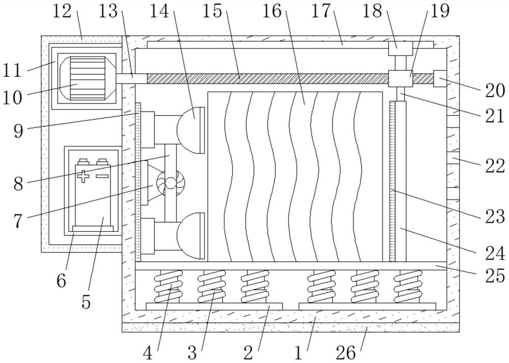
[0026] refer to Figure 1-2 , a medium-sized electromechanical equipment transport multi-position fixing device, comprising a box 1, a plurality of buffer shock absorbing mechanisms are provided on the inner wall of the bottom of the box body 1, and a support plate 25 is fixedly connected to the outer wall of the top of the buffer shock absorbing mechanism, A fixing frame 6 is fixed on the outer wall of one side of the box body 1 by bolts, and a battery 5 is clamped on the inner wall of the bottom of the fixing frame 6, and two motor frames 11 are fixed by bolts on one side of the outer wall of the box body 1 near the top. A motor frame 11 is located above the fixed frame 6, and a motor 10 is fixed by bolts on one side of the motor frame 11. One end of the output shaft of the motor 10 is keyed to a transmission shaft 13, and one end of the transmission shaft 13 is located at the bottom of the casing 1. Inside, one end of the transmission shaft 13 is provided with a limit clamp...

Embodiment 2

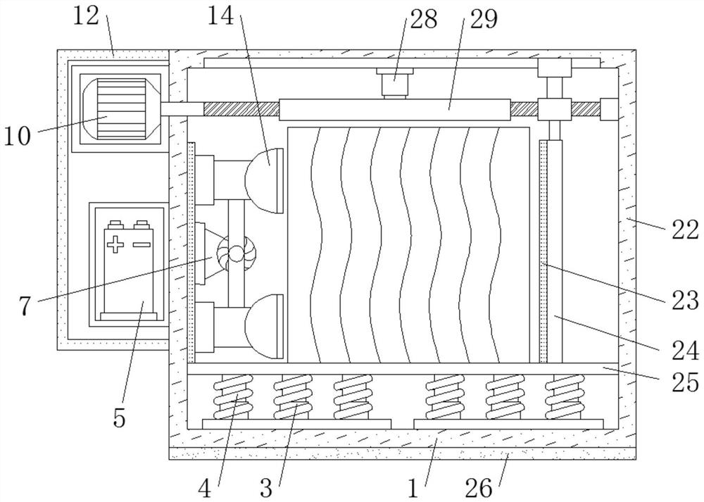
[0031] refer to image 3 , a multi-station fixing device for transportation of medium-sized electromechanical equipment. Compared with Embodiment 1, this embodiment also includes a pressure cylinder 28 and a pressure plate 29. The pressure cylinder 28 is fixed on the middle position of the inner wall of the top of the box body 1 by bolts, and the pressure plate 29 are fixed on one end of the extension rod of the pressure cylinder 28 by bolts.

[0032] When in use, there is also a pressing plate 29 on the inner wall of the top of the box body 1, and the pressing plate 29 is used to press and fix the surface of the electromechanical equipment, so that the transportation process of the electromechanical equipment is more stable.


PUM


Abstract

The invention discloses a multi-station fixing device used for medium-scale electromechanical device transportation. For the problem that it is not easy to solve electromechanical device shaking, thefollowing scheme is put forward. The multi-station fixing device comprises a box body. Multiple buffer shock absorption mechanisms are arranged on the inner wall of the bottom of the box body. The topouter walls of the buffer shock absorption mechanisms are fixedly connected with a supporting plate. A fixed frame is fixed to the outer wall of one side of the box body through bolts. A storage battery is connected to the bottom inner wall of the fixed frame in a clamping manner. Two motor frames are fixed to the position, close to the top, of the outer wall of one side of the box body through bolts. The two motor frames are located above the fixed frame. A motor is fixed to the inner wall of one side of each motor frame through bolts. One end of an output shaft of each motor is connected with a transmission shaft. According to the multi-station fixing device, a gas pump is started to make vacuum pads tightly attached to the surface of an electromechanical device to conduct fixation, then a vertical plate is squeezed on the other side of the electromechanical device to conduct pressurization and fixation, and a rubber pad and a soft pad are further arranged on the two sides to sufficiently protect the electromechanical device.

Description

technical field [0001] The invention relates to the technical field of fixing devices, in particular to a multi-station fixing device for transportation of medium-sized electromechanical equipment. Background technique [0002] Electromechanical equipment generally refers to machinery, electrical appliances, and electrical automation equipment. In construction, it refers to the general term for machinery and pipeline equipment other than geotechnical, carpentry, steel bars, and muddy water. It is different from hardware, which mostly refers to finished products that can achieve certain functions. Medium-sized electromechanical equipment needs to be transported by trucks for long-distance transportation, so it needs to use multi-station fixing devices for transportation. [0003] Most of the existing multi-station fixing devices for transportation of medium-sized electromechanical equipment in the market currently have the following deficiencies: electromechanical equipment i...

Claims


Application Information

Patent Timeline
IPC IPC(8): B65D25/10B65D85/68B65D81/05B65D25/02B65D81/07B60P7/16
CPCB60P7/16B65D25/02B65D25/10B65D81/05B65D81/052B65D81/07B65D85/68
Inventor 黄欣
Owner 大连赢得科技有限公司
Why Eureka
Try Eureka