Check patentability & draft patents in minutes with Patsnap Eureka AI!

Material mechanics deformation stress demonstration device with real-time image transmission function

A technology of material mechanics and deformation stress, applied in educational appliances, teaching models, instruments, etc., can solve the problems of not being able to take into account the four-side extrusion deformation stress demonstration, single test demonstration ability, and one-sided functions, etc., to achieve practicability Excellent, convenient switching operation, and the effect of improving compatibility

Active Publication Date: 2020-09-04
SHIJIAZHUANG UNIVERSITY
View PDF7 Cites 1 Cited by
  • Summary
  • Abstract
  • Description
  • Claims
  • Application Information

AI Technical Summary

Problems solved by technology

[0005] The purpose of the present invention is to provide a material mechanics deformation stress demonstration device with real-time image transmission, to solve the test demonstration ability proposed in the above background technology is relatively single, the function is relatively one-sided, and can not take into account the demonstration of four-sided extrusion deformation stress well and central top compression deformation stress demonstration issues

Method used


Image

  • Material mechanics deformation stress demonstration device with real-time image transmission function
  • Material mechanics deformation stress demonstration device with real-time image transmission function
  • Material mechanics deformation stress demonstration device with real-time image transmission function

Examples


Embodiment Construction

[0030] The following will clearly and completely describe the technical solutions in the embodiments of the present invention with reference to the accompanying drawings in the embodiments of the present invention. Obviously, the described embodiments are only some, not all, embodiments of the present invention.

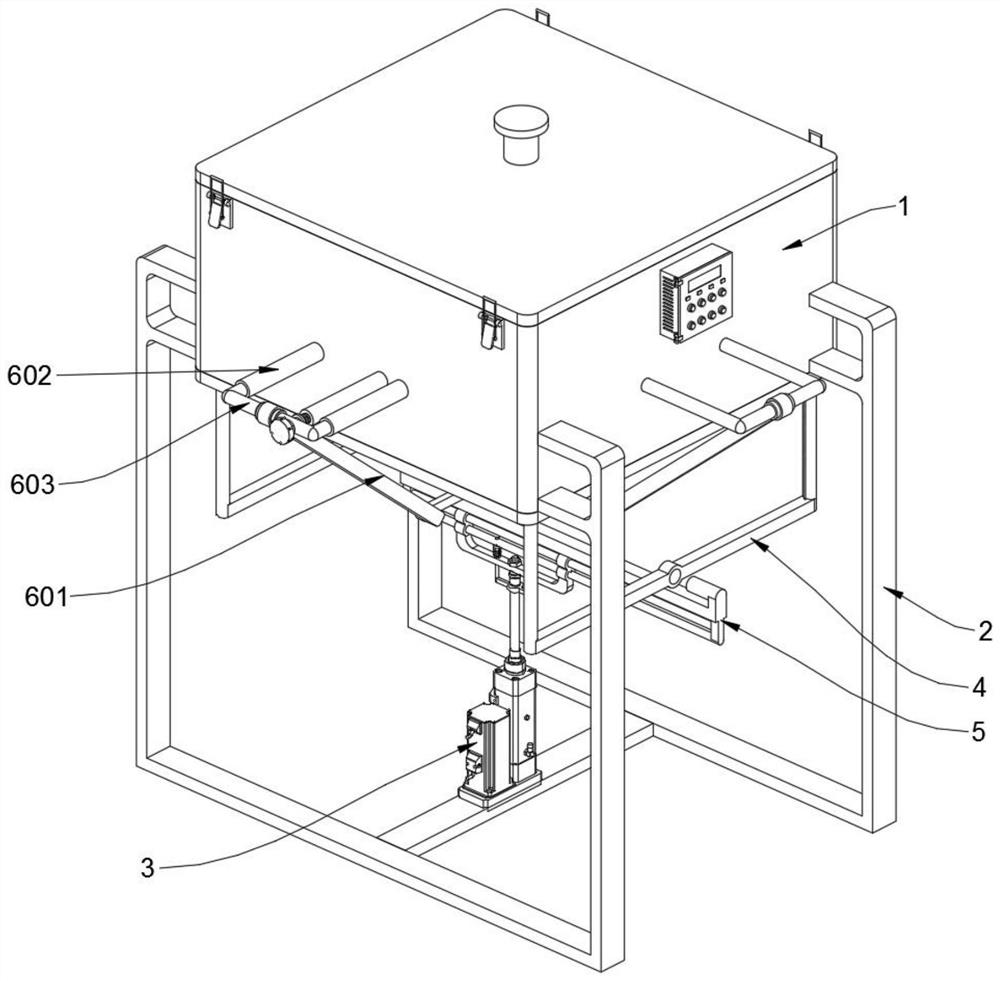
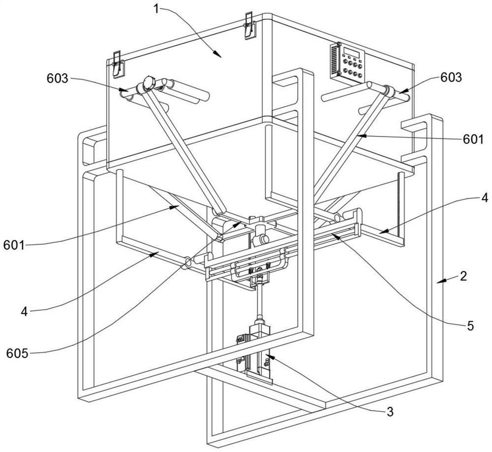
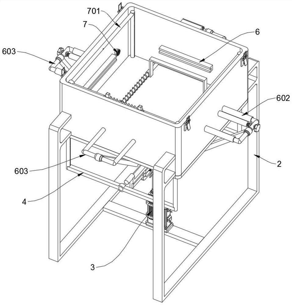
[0031] see Figure 1 to Figure 10, an embodiment provided by the present invention: a material mechanics deformation stress demonstration device with real-time image transmission, including a demonstration box 1, a synchronization frame 4 and a connecting frame 5, and the demonstration box 1 includes a cross brace positioning shaft 101 and a support Frame 102, the demonstration box 1 has a square structure as a whole, and its top is tightened to cover a transparent cover plate, and the bottom section of the front and rear inner walls of the demonstration box 1 is symmetrically supported with two horizontal brace positioning shafts 101. Two support frames 102 are inst...


PUM


Abstract

The invention discloses a material mechanics deformation stress demonstration device with a real-time image transmission function, belonging to the technical field of material testing and demonstration equipment. The device solves the problems that an existing demonstration device is relatively single in demonstration capability and relatively one-sided in function, and cannot well realize four-side extrusion deformation stress demonstration and central jacking deformation stress demonstration at the same time. The material mechanics deformation stress demonstration device with the real-time image transmission function comprises a synchronous frame and a connecting frame, wherein the whole demonstration box is of a square structure, the top end of the demonstration box is tightened and covered with a transparent cover plate, two transverse support positioning shafts are symmetrically supported on the bottom sections of the front and rear inner walls of the demonstration box, and two support frames are installed on the two transverse support positioning shafts in a sliding and sleeving mode; and the demonstration box is welded and fixed between the top end sections of two supportingleg frames. When four clamping plates slide in a gathered mode to extrude materials, the two supporting frames can be pushed to slide properly, so the front clamping plate and the rear clamping plateare prevented from being blocked, and normal implementation of mechanical deformation demonstration is guaranteed.

Description

technical field [0001] The invention relates to the technical field of material test demonstration equipment, in particular to a material mechanics deformation stress demonstration device equipped with real-time image transmission. Background technique [0002] Mechanics of materials is an important basic course for mechanical and civil engineering majors, and it is also a relatively abstract course, especially the content of the four basic deformation stresses of tension or compression, shearing, torsion and bending. It is difficult to truly understand with more vivid description and explanation methods. For example, for a simple bar shear deformation, students may understand the deformation characteristics of the shear deformation relatively easily, but they will feel a little powerless to let them really understand the shear stress distribution of the bar section. Therefore, in the teaching process of material mechanics, it is undoubtedly a good teaching method to use si...

Claims


Application Information

Patent Timeline
IPC IPC(8): G09B23/10
CPCG09B23/10
Inventor 杨蓓卢智嘉杨伟超杨凯
Owner SHIJIAZHUANG UNIVERSITY
Features
  • R&D
  • Intellectual Property
  • Life Sciences
  • Materials
  • Tech Scout
  • Unparalleled Data Quality
  • Higher Quality Content
  • 60% Fewer Hallucinations
Learn More