Labor-saving mute pressing rebound opening and closing device for furniture
An opening and closing device, mute technology, applied in furniture parts, home appliances, furniture accessories, etc., can solve the problems of affecting user experience, reducing product service life, low connection compactness, etc., to improve connection compactness, The effect of high stability and long service life
- Summary
- Abstract
- Description
- Claims
- Application Information
AI Technical Summary
Problems solved by technology
Method used
Image

Examples
Embodiment Construction
[0032] The present invention will be further described below in conjunction with the accompanying drawings and embodiments.
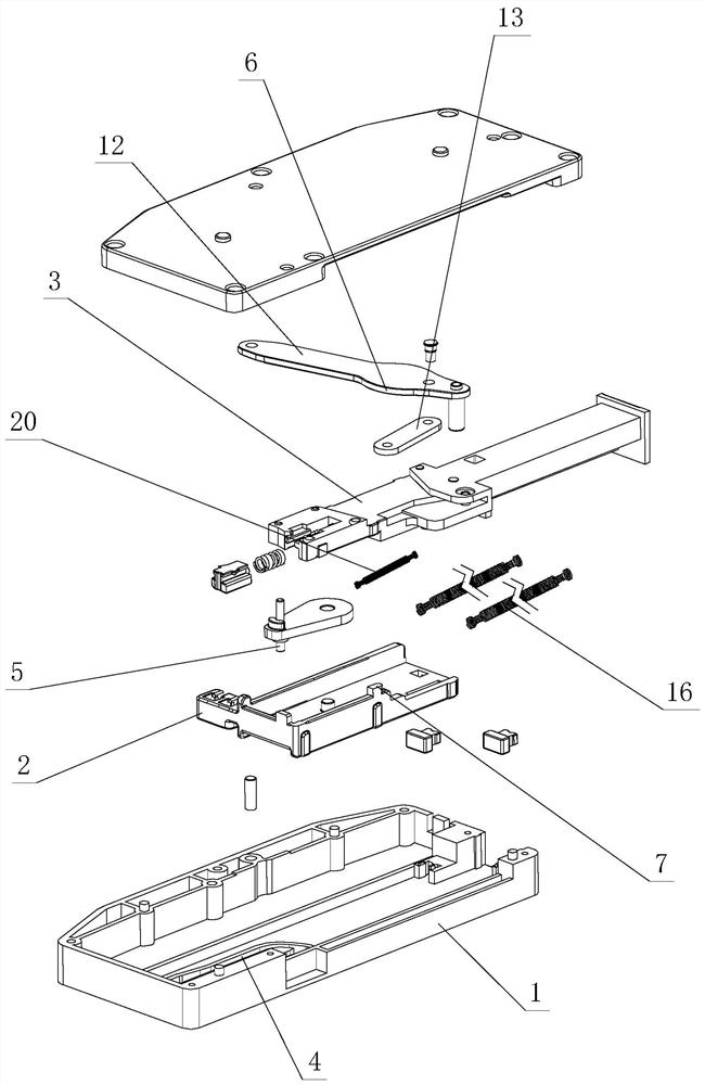
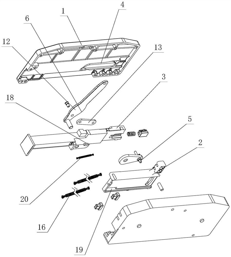
[0033] see Figure 1-Figure 13 , This furniture uses a labor-saving and silent push rebound opening and closing device, including a rebound bracket 1, a pushing element 2, a pressing element 3, and a lever assembly. The pressing element 3 elastically stretches and slides on the pushing element 2 and / or the rebound bracket 1 , and acts on and drives the sliding shaft portion 5 to position and / or slide along the track of the return-shaped groove 4 in a sequential direction when sliding.
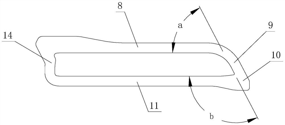
[0034] The lever assembly is connected with the rebound support 1 and the pressing element 3 respectively, and a lever action part 6 is also provided on it, a push action part 7 is provided on the push element 2, and an upper limit sliding area communicating with each other is at least provided on the back-shaped groove 4 8. Transition area 9 and former stop area 10.
...
PUM
 Abstract
Description
Claims
Application Information
 - Generate Ideas
- Intellectual Property
- Life Sciences
- Materials
- Tech Scout
- Unparalleled Data Quality
- Higher Quality Content
- 60% Fewer Hallucinations
Browse by: Latest US Patents, China's latest patents, Technical Efficacy Thesaurus, Application Domain, Technology Topic, Popular Technical Reports.
© 2025 PatSnap. All rights reserved.Legal|Privacy policy|Modern Slavery Act Transparency Statement|Sitemap|About US| Contact US: help@patsnap.com