Check patentability & draft patents in minutes with Patsnap Eureka AI!

Security element including micromirrors

A technology of anti-counterfeiting components and micro-mirrors, which can be applied to mirrors, printing, information-carrying cards, etc., and can solve the problems that the pattern effect cannot be realized, and the anti-counterfeiting components of micro-reflectors are difficult to copy.

Active Publication Date: 2021-12-28
GIESECKE & DEVRIENT CURRENCY TECHNOLOGY GMBH
View PDF12 Cites 0 Cited by
  • Summary
  • Abstract
  • Description
  • Claims
  • Application Information

AI Technical Summary

Problems solved by technology

[0006] Security elements with patterned micromirrors are difficult to reproduce, since such pattern effects are generally not possible with conventional printing techniques

Method used


Image

  • Security element including micromirrors
  • Security element including micromirrors
  • Security element including micromirrors

Examples


Embodiment Construction

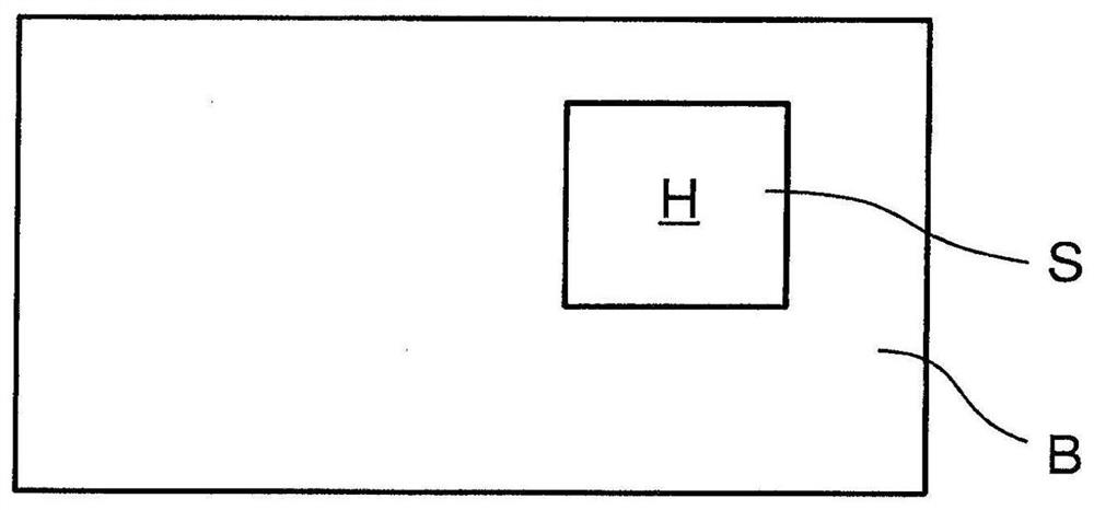
[0051] figure 1 A bank note B with a security element S is schematically shown. The banknote B comprises printed banknote paper, and the security element S is configured as a lamellar element which has been applied to the banknote paper. Due to the planar configuration of the security element S and the banknote B, the security element S defines a main plane H, which corresponds to figure 1 The drawing planes in .

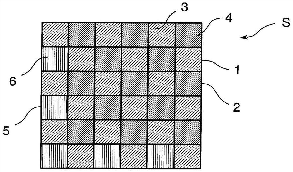
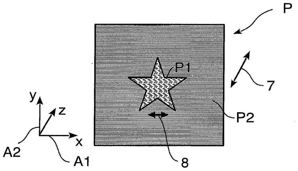
[0052] The security element S has a plurality of micromirrors, which present a pattern P with objects P1 , P3 to the observer in plan view. image 3 schematically shows a top view of a security element S with an object P1; Figure 4 An embodiment is concerned with two objects P1, P3.

[0053] In both cases, the security element S has two micromirror modes 1, 2, in figure 2 In the embodiment of , the two micromirror patterns are nested with each other in a checkerboard pattern, so that the horizontal and flat micromirror pixels 3 of the first micromirror patter...


PUM


Abstract

The invention relates to a flat security element comprising a micromirror, the flat security element (S) having a main plane (H) and micromirrors (3, 4) arranged as Micro-mirror patterns (1, 2) and present at least one design (P) that exhibits a design effect (7, 8) in relation to the principal plane (H), when said security element is tilted , the micro-mirror modes (1, 2) lead to the first and second design effects (7, 8), if the orientation of the security element is simultaneously around the secondary axis (A2) during the tilting movement around the major axis (A1) The first design effect (7) occurs within the range of the first inclination angle (10) of Within the angle range (11), the second design effect (8) appears.

Description

technical field [0001] The invention relates to a security element having a micromirror, wherein the micromirror is designed to present at least one object with a graphic effect. Background technique [0002] Optically variable effects are often used for security elements, especially for banknotes, passports or cards. Color-shifting effects can be achieved, for example, by means of color-shifting effect pigments or color-shifting multilayer structures. When changing the viewing angle of the security element, the color shifts or changes, for example from red to green. The second group of optically variable effects are tilted image effects. The image is only visible at one viewing angle and invisible at another viewing angle. In addition to these simple optically variable effects, there are also so-called gobo effects, in which the represented object moves (for example to appear flowing pattern transitions) or has a three-dimensional effect. [0003] In the prior art it is...

Claims


Application Information

Patent Timeline
Patent Type & Authority Patents(China)
IPC IPC(8): B42D25/324
CPCB42D25/324B42D25/36B42D25/425G02B5/09
Inventor K.H.谢雷尔R.德梅尔M.R.J.谢雷尔C.福斯
Owner GIESECKE & DEVRIENT CURRENCY TECHNOLOGY GMBH
Features
  • R&D
  • Intellectual Property
  • Life Sciences
  • Materials
  • Tech Scout
  • Unparalleled Data Quality
  • Higher Quality Content
  • 60% Fewer Hallucinations
Learn More