Unlock instant, AI-driven research and patent intelligence for your innovation.

Engine

An engine and mover technology, used in machines/engines, free-piston engines, mechanical equipment, etc., can solve the problems of high instantaneous power requirements, high noise, and unbalanced force of the motor instantaneous power supply, and achieve good energy saving and environmental protection. , Overcome the effect of high cost

Pending Publication Date: 2020-09-15
ENTROPY ZERO TECH LOGIC ENG GRP CO LTD
View PDF0 Cites 0 Cited by
  • Summary
  • Abstract
  • Description
  • Claims
  • Application Information

AI Technical Summary

Problems solved by technology

[0002] The traditional free-piston engine will cause unbalanced force during operation, which will cause strong working vibration and loud noise. Not only that, the traditional free-piston engine uses a motor to drive the piston to complete the power-consuming process such as the compression stroke, which will inevitably lead to The high requirements for the instantaneous power of the motor and the instantaneous power of the power supply lead to problems such as high cost, large volume, and heavy weight

Method used


Image

  • Engine
  • Engine
  • Engine

Examples


Embodiment 1

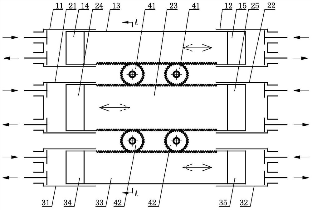
[0040] an engine such as figure 1 shown, including cylinder A 1 11. Cylinder A 2 12. Cylinder BC 1 21. Cylinder BC 2 22. Cylinder D 1 31. Cylinder D 2 32. The reciprocating mover A 13, the reciprocating mover BC 23, the reciprocating mover D 33, the transmission gear AB 41 and the transmission gear CD 42, the piston A is set on the reciprocating mover A 13 1 14 and Piston A 2 15. Set the piston BC on the reciprocating mover BC 23 1 24 and Piston BC 2 25. Set the piston D on the reciprocating mover D 33 1 34 and Piston D 2 35. The piston A 1 14 set in the cylinder A 1 11, the piston A 2 15 set in the cylinder A 2 12, the piston BC 1 24 set in the cylinder BC 1 21, the piston BC 2 25 set in the cylinder BC 2 22, the piston D 1 34 is provided in the cylinder D 1 31, the piston D 2 35 set in the cylinder D 2 32, the reciprocating mover A 13 is linked with the reciprocating mover BC 23 via the two transmission gears AB 41, and the recipr...

Embodiment 2

[0042] an engine such as figure 2 shown, including cylinder A 1 11. Cylinder A 2 12. Cylinder BC 1 21. Cylinder BC 2 22. Cylinder D 1 31. Cylinder D 2 32. The reciprocating mover A 13, the reciprocating mover BC 23, the reciprocating mover D 33, the transmission gear AB 41 and the transmission gear CD 42, the piston A is set on the reciprocating mover A 13 1 14 and Piston A 2 15. Set the piston BC on the reciprocating mover BC 23 1 24 and Piston BC 2 25. Set the piston D on the reciprocating mover D 33 1 34 and Piston D 2 35. The piston A 1 14 set in the cylinder A 1 11, the piston A 2 15 set in the cylinder A 2 12, the piston BC 1 24 set in the cylinder BC 1 21, the piston BC 2 25 set in the cylinder BC 2 22, the piston D 1 34 is provided in the cylinder D 1 31, the piston D 2 35 set in the cylinder D 2 32, the reciprocating mover A 13 is linked with the reciprocating mover BC 23 via the two transmission gears AB 41, and the recip...

Embodiment 3

[0049] an engine such as image 3 As shown, the difference from Embodiment 1 is that the transmission gear AB 41 is arranged in linkage with the rotational inertia body 5 , and the transmission gear CD 42 is arranged in linkage with another rotational inertia body 5 .

[0050] As an alternative embodiment, the third embodiment of the present invention can also selectively set the transmission gear CD42 in linkage with the rotational inertia body 5 (such as Figure 3.1 shown) or the transmission gear AB 41 is linked with the rotational inertia body 5 (such as Figure 3.2 shown).

[0051]As a changeable embodiment, the second embodiment of the present invention and its changeable embodiment and the changeable embodiment of the first embodiment can be further selectively selected to make the transmission gear AB 41 and the transmission gear CD 42 At least one of them is linked with the moment of inertia body 5 .

[0052] All the aforementioned embodiments of the present invent...


PUM


Abstract

The invention discloses an engine. A piston A1 and a piston A2 are arranged on a reciprocating rotor A; a piston BC1 and a piston BC2 are arranged on a reciprocating mover BC; a piston D1 and a pistonD2 are arranged on a reciprocating mover D; the piston A1 is arranged in an air cylinder A1; the piston A2 is arranged in an air cylinder A2; the piston BC1 is arranged in an air cylinder BC1; the piston BC2 is arranged in an air cylinder BC2; the piston D1 is arranged in an air cylinder D1; the piston D2 is arranged in an air cylinder D2; the reciprocating mover A is arranged in linkage with thereciprocating mover BC via a transmission gear AB; the reciprocating mover BC is arranged in linkage with the reciprocating mover D via a transmission gear CD; and the ratio of the diameter of the pistons on the reciprocating mover BC to the diameter of the pistons on the reciprocating mover A or the ratio of the diameter of the pistons on the reciprocating mover BC to the diameter of the pistonson the reciprocating mover D is between 1.35 and 1.5. The disclosed engine can effectively overcome the defects of high manufacturing price, large volume, high weight, and strong vibration of traditional flexible piston engines caused by imbalanced stress, and has good energy-saving and environmental-protection properties and good fuel adaptability.

Description

technical field [0001] The present invention relates to the field of thermal energy and power, in particular to an engine. Background technique [0002] The traditional free-piston engine will cause unbalanced force during operation, which will cause the disadvantages of strong working vibration and loud noise. Not only that, the traditional free-piston engine uses a motor to drive the piston to complete the power-consuming process such as the compression stroke, which will inevitably lead to The high requirements of the instantaneous power of the motor and the instantaneous power of the power supply lead to problems such as high cost, large volume and heavy weight. If it is possible to invent an engine in which the motion system is self-balanced and the power consumption process of the piston is solved by the inertial energy storage method of the motion system, such a high-efficiency engine as a free piston can be widely used, thereby improving the energy saving, environmen...

Claims


Application Information

Patent Timeline
Patent Type & Authority Applications(China)
IPC IPC(8): F02B71/00F02B71/04
CPCF02B71/00F02B71/04
Inventor 靳北彪
Owner ENTROPY ZERO TECH LOGIC ENG GRP CO LTD