Device used for large water level amplitude of reservoir, intercepting dirt and ensuring flood discharge and electricity generation safety

A reservoir water level and amplitude variable technology, applied in water conservancy projects, artificial waterways, coastline protection, etc., can solve problems such as difficult construction, large engineering quantity, and large anchorage pier size

Pending Publication Date: 2020-09-25
DALIAN UNIV OF TECH
0 Cites 2 Cited by

AI-Extracted Technical Summary

Problems solved by technology

[0013] Due to the use of buoys on the water, the traditional sewage blocking device often has a large water blocking area on the water surface, resulting in a large horizontal tension, resulting ...

Method used

As shown in Fig. 1 and Fig. 2, a kind of device that is used for reservoir water level variable amplitude is bigger, intercepts dirt, guarantees flood discharge and power generation safety, and this device comprises right bank slope 1, left bank slope 2, puts The anchor cable 3 and anchor head 5 inside the right bank slope 1 and the left bank slope 2, the concrete base 6 arranged at the foot of the right bank slope 1 and the left bank slope 2; The column 7 is connected with the anchor head 5 through the transverse connecting rod 4; a fixed intercepting net 8 is arranged between the column 7 and the slope 1 on the right bank, and between the column 7 and the slope 2 on the left bank; A floating interception net 15 is set between the columns 7 of the left bank slope 2; the floating interception net 15 c...

Abstract

The invention provides a device used for large water level amplitude of a reservoir, intercepting dirt and ensuring flood discharge and electricity generation safety. The device comprises a right bankslope, a left bank slope, an anchor cable, an anchor head and a concrete base, wherein the anchor cable and the anchor head are arranged in the right bank slope and the left bank slope, and the concrete base is arranged on the slope feet of the right bank slope and the left bank slope. Stand columns are arranged on the concrete base in a buried manner. The stand columns are connected with the anchor head through transverse connecting rods. A fixed intercepting net is arranged between the stand columns and the right bank slope and the left bank slope. A floating intercepting net is arranged between the stand columns of the right bank slope and the left bank slope. The floating intercepting net connects a sleeve ring with balls and the stand columns through a high-strength steel cable. An upper portion high-strength steel cable and a lower portion high-strength steel cable are arranged on the upper portion and the lower portion of the floating intercepting net correspondingly. The lowerportion high-strength steel cable is provided with a floating ball. The dirt floating on the water surface is intercepted through the floating intercepting net. The device can well adapt to the largewater level amplitude of the reservoir, the dirt can be effectively intercepted, during the flood discharge period, a flood discharge channel can be prevented from being blocked by the dirt, and theharm of dam flooding of flood is avoided.

Application Domain

Barrages/weirsArtificial water canals

Technology Topic

Geotechnical engineeringStructural engineering +5

Image

  • Device used for large water level amplitude of reservoir, intercepting dirt and ensuring flood discharge and electricity generation safety
  • Device used for large water level amplitude of reservoir, intercepting dirt and ensuring flood discharge and electricity generation safety

Examples

  • Experimental program(1)

Example Embodiment

[0020] The present invention will be further described in detail below in conjunction with the drawings and specific embodiments:
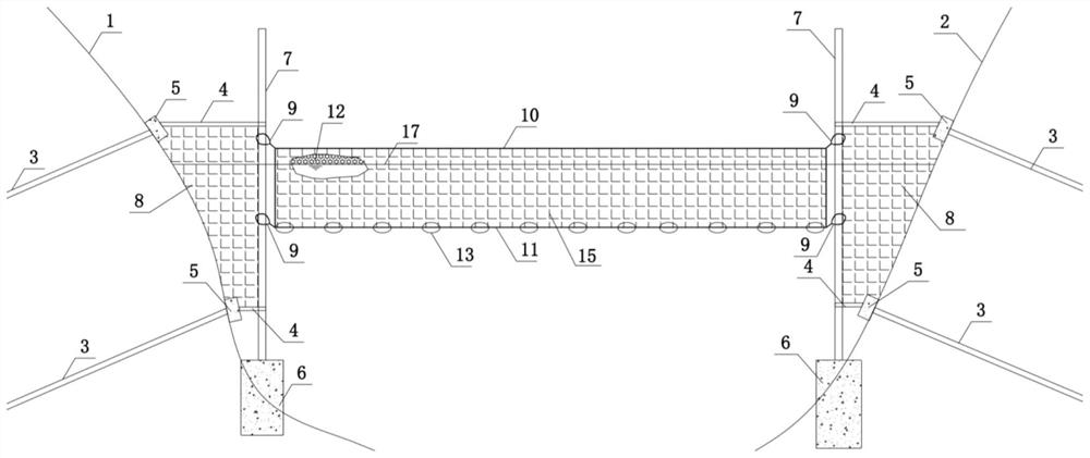
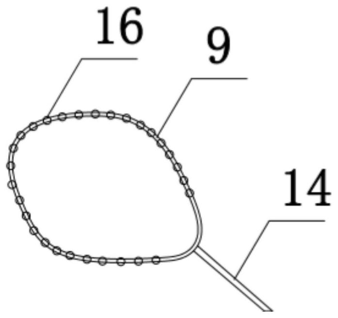
[0021] Such as figure 1 , figure 2 As shown, a device used for large changes in the water level of a reservoir, intercepting dirt, ensuring the safety of flood discharge and power generation, the device includes a right bank slope 1, a left bank slope 2, placed on the right bank slope 1 and the left bank The anchor cable 3 and the anchor head 5 inside the slope 2, the concrete base 6 set at the slope foot of the right bank slope 1 and the left bank slope 2; a column 7 is embedded on the concrete base 6, and the column 7 passes through a transverse connecting rod 4 is connected to the anchor head 5; a fixed interception net 8 is set between the column 7 and the right bank slope 1, between the column 7 and the left bank slope 2, and between the right bank slope 1 and the column 7 of the left bank slope 2 Set up a floating interception net 15; the floating interception net 15 connects the collar 9 with balls 16 to the column 7 through a high-strength steel cable 14; the upper and lower parts of the floating interception net 15 are respectively provided with an upper high-strength steel cable 10 and a lower high-strength steel cable 11. There is a float 13 on the lower high-strength steel cable 11, and the dirt 12 floating on the water surface 17 is intercepted by the floating interception net 15; this device can well adapt to the large water level fluctuation of the reservoir and effectively intercept the dirt. During flood discharge, it can prevent dirt from blocking the flood discharge channel, avoid the hazards of flooding the dam, and prevent the dirt from entering the turbine and affecting the safety of power generation.
[0022] The floating interception net 15 can be, but is not limited to, a high-strength reinforced warp-knitted geonet with a mesh size ≥ 10 cm.
[0023] The upper high-strength steel cable 10 and the lower high-strength steel cable 11 are braided by high-strength steel wires with a strength of ≥1500Mpa.
[0024] The material of the floating ball 13 may be, but not limited to, polyethylene plastic balls, and the number of floating balls 13 is calculated by buoyancy.
[0025] The height of the floating interception net 15 above the water surface 17 is ≥50cm.
[0026] The said column 7 is made of steel pipe with a diameter ≥10cm, and the height is determined according to the amplitude of the water level.
[0027] The following is a detailed description. In this embodiment, the construction is carried out according to the following steps: firstly construct anchor cables and anchor piers on both banks of the reservoir, construct foundations and columns on the left and right banks in front of the dam, and pass through the anchor piers of the cross bars and the anchor cables on the mountain. The steel plates embedded in the concrete are connected, and the interception net is set between the columns. The interception net is 50cm above the water surface. There is a floating ball on the net. The floating ball is located in the underwater part, so that the interception net can float freely as the water level changes. The interception net and the column are adopted The collar connection with balls allows the interception net to slide up and down the column freely as the water level changes, so as to achieve the purpose of intercepting water surface dirt, and the entire construction is completed.
[0028] The above examples are only used to illustrate the technical ideas and features of the present invention. Its purpose is to enable those skilled in the art to understand the content of the present invention and implement them accordingly. This example cannot be used to limit the patent scope of the present invention, namely Any equivalent changes or modifications made to the spirit disclosed in the present invention still fall within the scope of the patent of the present invention.

PUM

PropertyMeasurementUnit
Strength>= 1500.0mPa
Diameter>= 10.0cm

Description & Claims & Application Information

We can also present the details of the Description, Claims and Application information to help users get a comprehensive understanding of the technical details of the patent, such as background art, summary of invention, brief description of drawings, description of embodiments, and other original content. On the other hand, users can also determine the specific scope of protection of the technology through the list of claims; as well as understand the changes in the life cycle of the technology with the presentation of the patent timeline. Login to view more.
Why Eureka
Try Eureka