Pneumatic strain energy accumulator and control method thereof

A technology of strain energy and accumulators, applied in accumulator devices, fluid pressure actuating devices, mechanical equipment, etc., to achieve the effects of smooth air intake/deflation, increased energy storage density, and increased energy storage

Active Publication Date: 2020-10-02
DALIAN MARITIME UNIVERSITY
View PDF5 Cites 1 Cited by
  • Summary
  • Abstract
  • Description
  • Claims
  • Application Information

AI Technical Summary

Problems solved by technology

Existing accumulators cannot meet these requirements due t

Method used


Image

  • Pneumatic strain energy accumulator and control method thereof

Examples


Example Embodiment

[0030] The technical solutions in the embodiments of the present invention will be clearly and completely described below in conjunction with the accompanying drawings in the embodiments of the present invention. Obviously, the described embodiments are only a part of the embodiments of the present invention, rather than all the embodiments. Based on the embodiments of the present invention, all other embodiments obtained by those of ordinary skill in the art without creative work shall fall within the protection scope of the present invention.
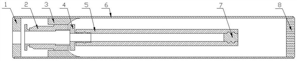
[0031] The purpose of the present invention is to provide a pneumatic strain energy accumulator and its control method to solve the problems existing in the prior art. The rigid round tube is used to limit the radial expansion of the elastic air bag tube, so that the elastic air bag tube will generate axis earlier. To strain to increase the energy storage density.

[0032] In order to make the above-mentioned objects, features and advantag...


PUM


Abstract

The invention discloses a pneumatic strain energy accumulator and a control method thereof. The accumulator comprises a rigid round pipe, a fixed ring fixedly arranged on the inner wall of the rigid round pipe and an elastic air bag pipe arranged at the interior of the rigid round pipe; the elastic air bag pipe comprises an open end and a closed end, wherein the open end is connected with a quick-change connector, and the quick-change connector is connected with the fixed ring in a sliding mode; and the inner diameter of the rigid round pipe is smaller than the limit diameter of deformation ofthe elastic air bag pipe. According to the accumulator and the method, the rigid round pipe is used for limiting the radial expansion of the elastic air bag pipe, and the rigid round pipe can limit the radial deformation of the elastic air bag pipe, so that the situation that the elastic air bag pipe is early fatigued caused by excessive deformation, and then the service life is shortened can beprevented; the axial strain of the elastic air bag pipe can be early generated by limiting the radial strain of the elastic air bag pipe, and thus the energy storage density is increased; and in addition, the sliding connection mode between the quick-change connector and the fixed ring can guarantee that the axis of the open end of the elastic air bag pipe coincides with the axis of the rigid round pipe, and then smooth air inlet/outlet is guaranteed.

Description

technical field [0001] The invention relates to the technical field of accumulators, in particular to a pneumatic strain energy accumulator and a control method thereof. Background technique [0002] An accumulator is an energy storage device in a pneumatic / hydraulic system. It converts the energy in the system into compression energy or potential energy at an appropriate time and stores it. When the system needs it, it converts the compression energy or potential energy into Hydraulic or pneumatic energy is released to replenish the supply system, and the accumulator also has the function of buffering and shock absorption. [0003] The accumulator in the existing pneumatic field is mainly a gas tank with a rigid structure. The gas volume is reduced by low temperature and high pressure to achieve the purpose of gas storage. The disadvantage is that the structural strength and sealing of the gas tank are high, and the energy density Low, and cannot output energy at a steady ...

Claims


Application Information

Patent Timeline
IPC IPC(8): F15B1/027F15B1/08
CPCF15B1/027F15B1/08Y02E60/16
Inventor 度红望杨冬冬熊伟王海涛马文琦关广丰孙长乐王志文
Owner DALIAN MARITIME UNIVERSITY
Why Eureka
Try Eureka