Tool clamp of motor end cover capable of alternately working

A technology of motor end cover and tooling fixture, which is applied in the direction of manufacturing tools, metal processing machinery parts, metal processing equipment, etc., can solve the problem of inconvenient clamping of motor end cover, and achieve simple structure, convenient clamping and high production efficiency Effect

Inactive Publication Date: 2020-10-09
官文亮
View PDF0 Cites 0 Cited by
  • Summary
  • Abstract
  • Description
  • Claims
  • Application Information

AI Technical Summary

Problems solved by technology

[0003] The purpose of the present invention is to provide a tooling fixture for alternately working

Method used


Image

  • Tool clamp of motor end cover capable of alternately working
  • Tool clamp of motor end cover capable of alternately working

Examples


Example Embodiment

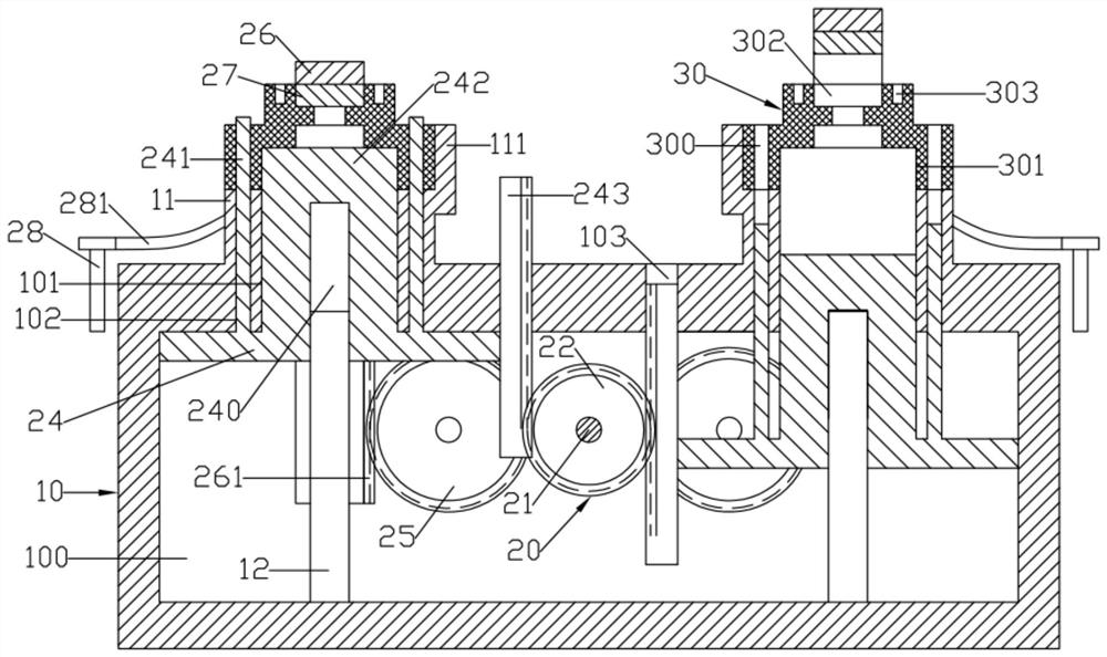
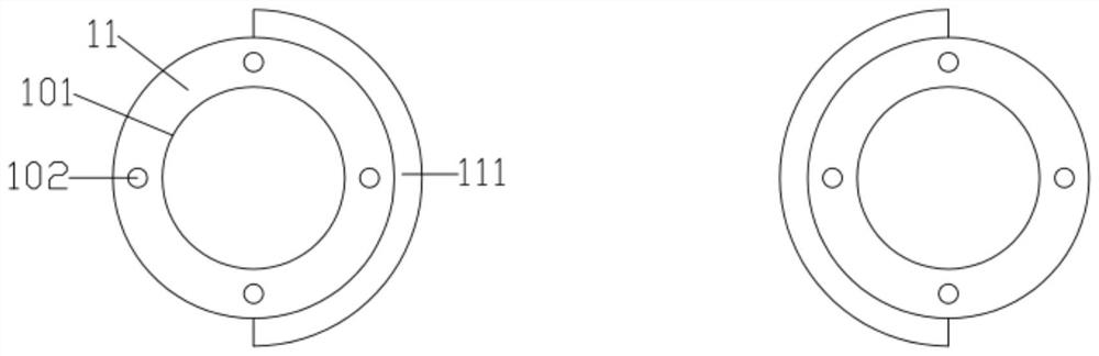
[0014] Such as figure 1 , figure 2 As shown, a tooling fixture for an alternately working motor end cover includes a rectangular parallelepiped support base 10 and an alternate limit device 20; the support base 10 is formed with a rectangular groove-shaped drive groove 100 inside; the upper end surface of the support base 10 A pair of symmetrical cylindrical mounting bases 11 are formed on the upper surface; the center of the upper end surface of the mounting base 11 is formed with a central lifting hole 101 penetrating downwards; the upper end surface of the mounting base 11 is formed with a number of uniform circumferences. Distributed downwardly penetrating round-hole-shaped limiting column lifting holes 102; a semicircular cylindrical blocking ring 111 is formed at one end of the outer cylindrical surface of a pair of placement bases 11 close to each other; the alternate limiting device 20 includes a The lifting support plate 24 is set up for lifting and the upper limit se...


PUM


Abstract

The invention discloses a tool clamp of a motor end cover capable of alternately working. Semi-circular cylindrical blocking rings are formed at the ends, close to each other, of the outer cylindricalsurfaces of a pair of placement seats; an alternate limiting device comprises a pair of lifting supporting plates which are symmetrically arranged left and right and a pair of U-shaped upper limitingseats which are arranged in a lifting mode and provided with downward openings; the lifting directions of the pair of lifting supporting plates are opposite; a cylindrical center limiting column matched with a center lifting hole is formed on the upper end face of each lifting supporting plate; a plurality of side limiting columns matched with limiting column lifting holes are formed on the upperend face of each lifting supporting plate; the pair of upper limiting seats are vertically inserted into a supporting seat; the placement seats are positioned in the upper limiting seat on the corresponding side; the lifting direction of each upper limiting seat is opposite to that of the lifting supporting plate on the corresponding side; and a circular-plate-shaped upper limiting inserting block is formed in the center of the lower end face of a longitudinal part of each upper limiting seat.

Description

technical field [0001] The invention relates to the technical field of motor end cover processing, in particular to a tooling fixture for an alternately working motor end cover. Background technique [0002] A kind of motor end cover 30, its structure is as figure 1 As shown, the center of the lower end surface of the motor end cover 30 is formed with a center limit hole 301; the periphery of the motor end cover 30 is formed with an installation perforation 300; the center of the upper end surface of the motor end cover 30 is formed with an external connection groove 302; the motor end cover 30 There are several uniformly distributed threaded holes 303 formed on the upper end surface of the motor; before the threaded holes are processed, the motor end cover needs to be clamped on the tooling, and the reliability and efficiency of the clamping directly affect the product quality and output. At present, the traditional tooling used is cumbersome to operate, unstable in qualit...

Claims


Application Information

Patent Timeline
IPC IPC(8): B23Q1/66
CPCB23Q1/66
Inventor 官文亮
Owner 官文亮
Why Eureka
Try Eureka