Check patentability & draft patents in minutes with Patsnap Eureka AI!

Computer network tapping device

A computer network and filter technology, which is applied to the parts of the connection device, the coupling device, the connection, etc., can solve the problems of the filter blockage of the cooling fan, the decrease of the heat dissipation capacity, and the fixation, so as to avoid the damage of the network cable and avoid easy loosening , to avoid the effect of damage

Active Publication Date: 2020-10-09
XUCHANG UNIV
View PDF8 Cites 2 Cited by
  • Summary
  • Abstract
  • Description
  • Claims
  • Application Information

AI Technical Summary

Problems solved by technology

[0003] When the existing computer network branching device is in use, due to the existence of multiple network ports, multiple network cables can be connected, and the connection direction of each network cable is different. When the bending angle is too large, the network cable is easily damaged, and , the existing network splitter cannot fix the inserted network cable, the network cable is easy to be loosened and pulled out, and it is also easy to cause damage to the slot of the network splitter, and when the existing network splitter is in use, the heat generated Larger, some network taps use cooling fans for heat dissipation, but the filter screen of the cooling fan is blocked by dust, resulting in a decrease in cooling capacity

Method used


Image

  • Computer network tapping device
  • Computer network tapping device
  • Computer network tapping device

Examples


Embodiment 1

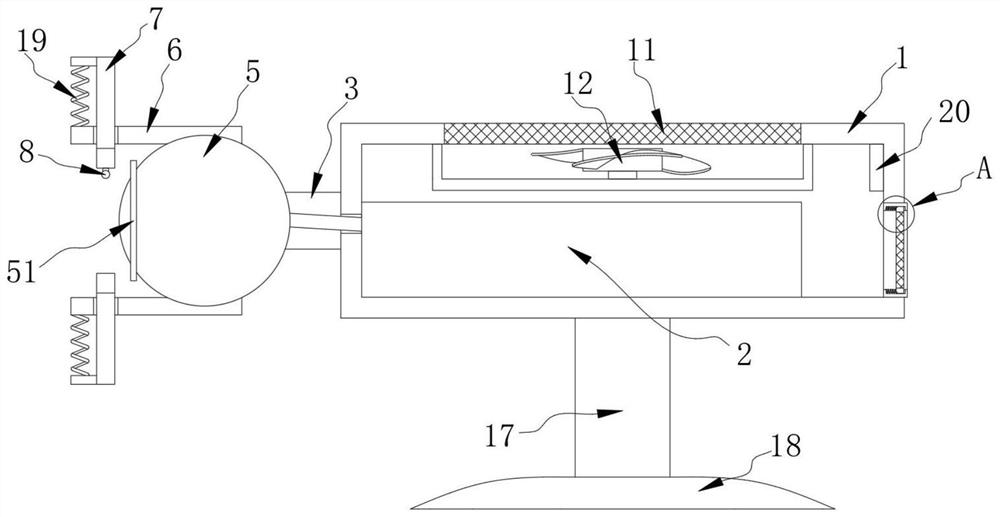
[0031] like figure 1 , figure 2 , image 3 , Figure 4 , Figure 5 , Figure 6 and Figure 7 shown;

[0032] figure 1 It is a schematic diagram of the overall structure of the present invention;

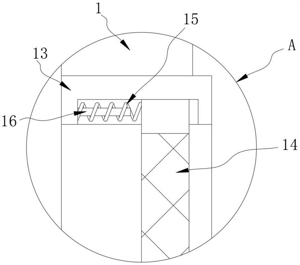
[0033] figure 2 for the present invention figure 1 Schematic diagram of the structure at A;

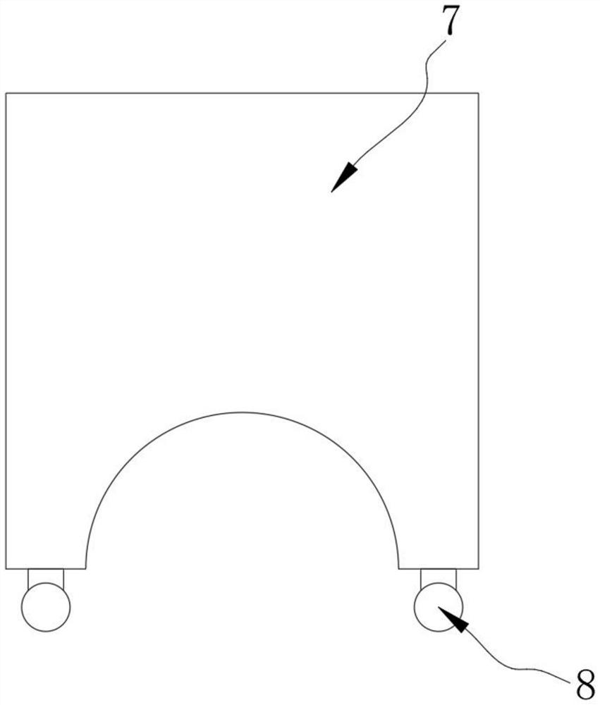
[0034] image 3 It is a schematic diagram of the installation structure of the clamping plate and the clamping block in the present invention;

[0035] Figure 4 It is a schematic diagram of the installation structure of the rubber pad and the clamping plate in the present invention;

[0036] Figure 5 is the front view in the present invention;

[0037] Figure 6 It is a top view in the present invention;

[0038] Figure 7 for the present invention Figure 6 Schematic diagram of the structure at B;

[0039] A computer network branching device, comprising a housing 1, a network tap controller 2 is fixedly connected to the inner left end of the bottom end surface of the...


PUM


Abstract

The invention belongs to the technical field of machinery, and especially relates to a computer network tapping device. The device comprises a shell, wherein the left end of the inner side of the bottom end surface of the shell is fixedly connected with a network tapping controller; the left end face of the shell is fixedly connected with a support; the left end face of the support is fixedly connected with a cambered surface clamping plate; the support and the cambered surface clamping plate form a clamping assembly; a mounting block is arranged between the clamping assemblies; a network portis formed in the mounting block; the network port is communicated with the network tapping controller through an optical fiber cable; the optical fiber cable penetrates through the shell and is in sliding connection with the shell; and fixing plates are fixedly connected to the top end face of the mounting block and the bottom end face of the mounting block. Through the arrangement of the supportand the cambered surface clamping plates, the mounting block can rotate between the two cambered surface clamping plates, and after a user inserts a network cable into the network port in the corresponding mounting block, the mounting block can change the orientation of the mounting block within a certain range along with the change of the connection direction of the network cable, so that the situation that the bending angle of the network cable is too large is avoided, and the network cable is prevented from being damaged.

Description

technical field [0001] The invention belongs to the technical field of machinery, and in particular relates to a computer network branching device. Background technique [0002] The simplest definition of a computer network is: a collection of interconnected, autonomous computers for the purpose of sharing resources. [0003] When the existing computer network branching device is in use, due to the existence of multiple network ports, multiple network cables can be connected, and the connection direction of each network cable is different. When the bending angle is too large, the network cable is easily damaged, and , the existing network splitter cannot fix the inserted network cable, the network cable is easy to be loosened and pulled out, and it is also easy to cause damage to the slot of the network splitter. Moreover, when the existing network splitter is in use, the heat generated Larger, some network taps use cooling fans for heat dissipation, but the filter screen o...

Claims


Application Information

Patent Timeline
IPC IPC(8): H01R13/639H05K7/20H05K5/02
CPCH01R13/639H05K5/0247H05K7/20172H05K7/20181H05K7/20209H05K5/0213H05K5/03
Inventor 孟耀伟
Owner XUCHANG UNIV
Features
  • R&D
  • Intellectual Property
  • Life Sciences
  • Materials
  • Tech Scout
  • Unparalleled Data Quality
  • Higher Quality Content
  • 60% Fewer Hallucinations
Learn More