Automatic material conveying structure of industrial automation equipment and operation method

An industrial automation and automatic transmission technology, which is applied to conveyor objects, conveyors, transportation and packaging, etc., can solve the problems of occupying space and uneven conveying materials, and achieve the effect of convenient conveying, good effect, and uniform conveying materials.

Inactive Publication Date: 2020-10-13
新乡市烛龙微电子技术有限公司
0 Cites 1 Cited by

AI-Extracted Technical Summary

Problems solved by technology

Under the conditions of industrial production automation, people only take care of and supervise the production of machines indirectly, but in the existing industrial automation equipment automatic material transmission equipment, it is often necess...

Abstract

The invention discloses an automatic material conveying structure of industrial automation equipment and an operation method. The automatic material conveying structure comprises a material lifting mechanism, a supporting bottom frame, a horizontal conveying device, a material scraping assembly, a rotating and adjusting assembly, an adjusting and conveying assembly and a sliding assembly, whereinthe supporting bottom frame comprises a U-shaped bottom frame and universal guide wheels arranged at the four corners of the lower surface of the U-shaped bottom frame, and a supporting frame of the material lifting mechanism is fixed to the right end of the upper surface of the U-shaped bottom frame through bolts. A second rotating shaft can be driven to rotate through a fourth motor, a second conveying belt can be driven to rotate through the second rotating shaft, secondary conveying of materials can be achieved through the second conveying belt, so that conveying is more convenient, the conveyed materials can be scraped to be flat, then the conveyed materials are more uniform, the material conveying effect is better, the conveying direction can be adjusted, the conveying length can beadjusted, and convenience is provided for people.

Application Domain

ConveyorsPackaging +2

Technology Topic

Electric machineryManufacturing engineering +6

Image

  • Automatic material conveying structure of industrial automation equipment and operation method
  • Automatic material conveying structure of industrial automation equipment and operation method
  • Automatic material conveying structure of industrial automation equipment and operation method

Examples

  • Experimental program(1)

Example Embodiment

[0028] The technical solutions in the embodiments of the present invention will be clearly and completely described below with reference to the accompanying drawings in the embodiments of the present invention. Obviously, the described embodiments are only a part of the embodiments of the present invention, but not all of the embodiments. Based on the embodiments of the present invention, all other embodiments obtained by those of ordinary skill in the art without creative efforts shall fall within the protection scope of the present invention.
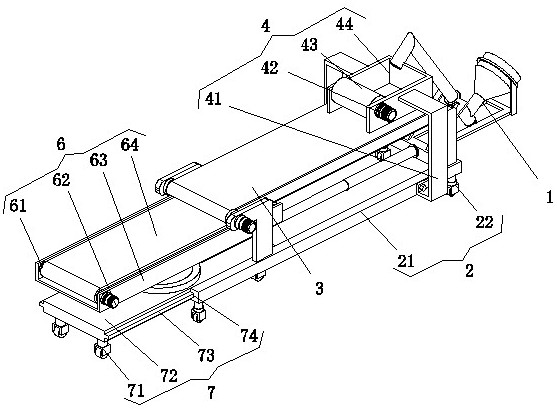
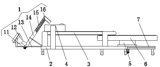
[0029] see Figure 1-4 , The present invention provides a technical solution: a structure and operation method for automatic material transmission by industrial automation equipment, including a material lifting mechanism 1, a supporting chassis 2, a horizontal conveying device 3, a scraping component 4, a rotating adjustment component 5, and adjustment and conveying. assembly 6 and sliding assembly 7;
[0030] Supporting chassis 2: The supporting chassis 2 includes a U-shaped chassis 21 and universal guide wheels 22 arranged at the four corners of the lower surface of the U-shaped chassis 21;
[0031] Material lifting mechanism 1: The support frame 13 of the material lifting mechanism 1 is fixed on the right end of the upper surface of the U-shaped base frame 21 by bolts. The material lifting mechanism 1 includes an L-shaped feeding tube 14 placed obliquely, and the interior of the L-shaped feeding tube 14 passes through a bearing A feeding shaft 16 is connected, the outer side of the feeding shaft 16 is provided with a screw feeding blade 15, the lower end of the L-shaped feeding tube 14 is connected with a motor 11 that drives the feeding shaft 16 to rotate, and the lower end of the L-shaped feeding tube 14 is connected with a feeding port 11. A conical structure hopper 12 is arranged on the side, a support frame 13 is arranged between the upper end of the hopper 12 and the L-shaped feeding pipe 14, and the input end of the motor one 11 is electrically connected with the output end of the external control switch;
[0032] Horizontal conveying device 3: The horizontal conveying device 3 includes two sets of support foot plates 33 arranged on the left and right sides of the upper surface of the U-shaped base frame 21. The upper ends of each group of support foot plates 33 are connected with a rotating shaft 32 through bearings, and the two rotating shafts are one. There is a conveyor belt 34 between 32, the end of the conveyor belt 34 is located below the left end of the material lifting mechanism 1, and one side of the supporting foot plate 33 is provided with a motor two 31 that drives the rotation shaft one 32. The input end of the motor two 31 is connected to the The output terminal of the external control switch is electrically connected;
[0033] Scraper assembly 4: The scraper assembly 4 is arranged above the conveyor belt 1 34, and the scraper assembly 4 corresponds to the discharge port of the L-shaped feeding pipe 14 of the material lifting mechanism 1 up and down. The scraper assembly 4 includes the lower end and the conveyor belt 34. Surface-fitted U-shaped protective frame 44, the left side of the U-shaped protective frame 44 is connected with a flattening roller 43 through a bearing, and one side of the U-shaped protective frame 44 is provided with a motor three 42 that drives the flattening roller 43 to rotate, U-shaped The front and rear sides of the protective frame 44 are provided with L-shaped mounting feet 41 connected with the U-shaped chassis 21 by bolts, and the input end of the motor three 42 is electrically connected with the output end of the external control switch;
[0034]Sliding assembly 7: The two sliding grooves 74 of the sliding assembly 7 are arranged on the opposite sides of the two transverse rods of the U-shaped chassis 21, and the sliding plate 72 side of the sliding assembly 7 is aligned with the longitudinal rod of the U-shaped chassis 21. A hydraulic telescopic column 8 is connected between the sides by bolts, and the inlet of the hydraulic telescopic column 8 is connected with the outlet of the external hydraulic pump through an oil pipe. The connecting plate 72, the front and rear sides of the sliding connecting plate 72 are provided with sliding connecting strips 73 slidably connected with the sliding connecting groove 74, and the four corners of the lower surface of the sliding connecting plate 72 are provided with supporting guide wheels 71;
[0035] Rotation adjustment assembly 5: The rotation adjustment assembly 5 is arranged at the center of the upper surface of the sliding plate 72, and the rotation adjustment assembly 5 includes a rotary support ring 53 provided on the upper surface of the sliding plate 72, and the upper end of the rotary support ring 53 is provided with a support tube 51 , the lower surface of the sliding plate 72 is provided with an angle motor 52 that drives the support tube 51 to rotate, and the input end of the angle motor 52 is electrically connected to the output end of the external control switch;
[0036] Wherein: it also includes an adjustment conveying assembly 6, and the adjustment conveying assembly 6 includes a U-shaped support frame 63 connected with the upper end of the support pipe 51 of the rotation adjustment assembly 5 through bolts, and the two ends of the U-shaped support frame 63 are connected with a rotating shaft two 61 through bearings, A conveyor belt 2 64 is arranged between the two rotating shafts 61 , and a motor 4 62 drives the rotating shaft 2 61 to rotate on one side of the U-shaped support frame 63 . The input end of the motor 4 62 is electrically connected to the output end of the external control switch.
[0037] An operation method for automatic transmission of material structure by industrial automation equipment, comprising the following steps:
[0038] S1) Lengthening adjustment or steering adjustment: When lengthening adjustment, the first choice is to extend through the hydraulic telescopic column 8 to drive the sliding plate 72 to slide out from the middle of the U-shaped base frame 21, so as to adjust the whole of the conveying assembly 6 and the horizontal conveying device 3. The distance is adjusted to adjust the length of the transmission. When the steering is adjusted, the hydraulic telescopic column 8 is extended to drive the sliding plate 72 to slide out from the middle of the U-shaped chassis 21, and then the angle motor 52 can drive the support tube 51 to rotate. The pipe 51 can drive the adjustment conveying assembly 6 to rotate, so that the conveyor belt 2 64 of the adjustment conveying assembly 6 is perpendicular to the conveyor belt 1 34, and then shortened by the hydraulic telescopic column 8 to drive the conveyor belt 2 64 to move below the left end of the conveyor belt 1 34, so as to realize steering function;
[0039] S2) Material lifting: When conveying materials, it is preferred to prevent the material from entering the inside of the hopper 12, and then drive the feeding shaft 16 to rotate through the motor 11, and drive the screw feeding blade 15 to rotate through the feeding shaft 16. The feeding pipe 14 cooperates to convey the material to the upper surface of the conveyor belt 1 34 and is located inside the U-shaped protective frame 44;
[0040] S3) Primary conveying: then the motor 2 31 drives the rotating shaft 1 32 to rotate, and the rotating shaft 1 32 drives the conveyor belt 1 34 to rotate. The conveyor belt 1 34 can realize the primary conveying of the material, and the conveyor belt 1 34 conveys the raw materials to the conveyor belt. The upper surface of the second 64, during the first-level conveying, is driven by the motor three 42 to drive the scraping roller 43 to rotate, and the scraping roller 43 can scrape the material conveyed on the upper surface of the conveyor belt one 34, so that the conveyed material is more uniform, and the The material conveying effect is better;
[0041] S4) Secondary conveying: the second shaft 61 can be driven to rotate by the motor four 62, the second conveyor belt 64 can be driven to rotate through the second rotating shaft 61, and the material can be conveyed in two stages through the second conveyor belt 64, so as to transport the material to the corresponding position .
[0042] Although embodiments of the present invention have been shown and described, it will be understood by those skilled in the art that various changes, modifications, and substitutions can be made in these embodiments without departing from the principle and spirit of the invention and modifications, the scope of the present invention is defined by the appended claims and their equivalents.

PUM

no PUM

Description & Claims & Application Information

We can also present the details of the Description, Claims and Application information to help users get a comprehensive understanding of the technical details of the patent, such as background art, summary of invention, brief description of drawings, description of embodiments, and other original content. On the other hand, users can also determine the specific scope of protection of the technology through the list of claims; as well as understand the changes in the life cycle of the technology with the presentation of the patent timeline. Login to view more.

Similar technology patents

Foldable tripod, building template and scaffold

ActiveCN101769067Aeasy to transport
Owner:北京卓良模板有限公司

Electric pole

InactiveCN104453329Aeasy to transport
Owner:STATE GRID CORP OF CHINA +1

Oligosaccharides plant induced-resistance agent effervescent tablet and preparation method thereof

ActiveCN101653149Aeasy to dissolveeasy to transport
Owner:深圳市沃科生物工程有限公司

Assembling system

Owner:双杰电气合肥有限公司

Classification and recommendation of technical efficacy words

  • Easy to transport

X-shaped self-heat insulating building block

InactiveCN102345339Aeasy to transportEasy to mold
Owner:李精华

Inorganic multifunctional paint taking potassium silicate as film-forming substance, and preparation method thereof

InactiveCN103709799Aeasy to transportfor long-term storage
Owner:GUANGZHOU WEIDUONA ENVIRONMENTAL PROTECTION TECH

Internal curing material of high-performance concrete and preparation method thereof

InactiveCN102390951AEasy to transport and useeasy to transport
Owner:RAILWAY ENG RES INST CHINA ACADEMY OF RAILWAY SCI
Why Eureka
Try Eureka