
Method for improving basic waterproof performance of wind generating set

A wind turbine, basic technology, applied in wind turbines, installation/support configuration of wind turbines, wind power generation, etc., can solve problems such as water leakage in waterproof structures, and achieve the effect of ensuring waterproof performance

Pending Publication Date: 2020-10-16
HUNAN THERMAL POWER CONSTR CO LTD OF CHINA ENERGY ENG GRP
View PDF12 Cites 1 Cited by
  • Summary
  • Abstract
  • Description
  • Claims
  • Application Information

AI Technical Summary

Problems solved by technology

[0006] The technical problem to be solved by the present invention is to provide a method for improving the waterproof performance of the foundation of the wind power generating set in view of the defect that the existing waterproof structure slides downward under the action of gravity to cause water leakage

Method used


Image

  • Method for improving basic waterproof performance of wind generating set
  • Method for improving basic waterproof performance of wind generating set
  • Method for improving basic waterproof performance of wind generating set

Examples


Embodiment 1

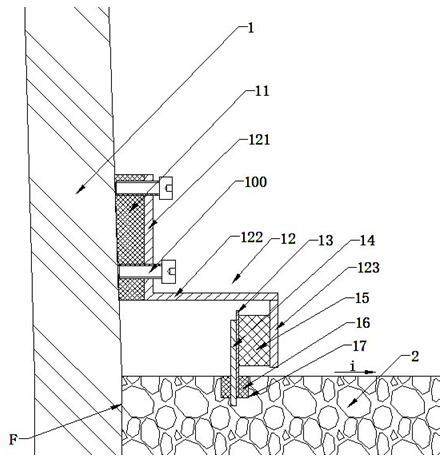
[0036] The manufacturing steps of the water guide plate 12 in the first embodiment are as follows:

[0037] Step 1. Manufacturing the water retaining plate 13:

[0038] A1. At a distance of 45 mm from the outer wall of the foundation ring 1, there is an annular groove 17 with a width of 20 mm. The depth of the annular groove 17 is determined according to the surface structure of the foundation cap 2. If there is no secondary plastering layer on the surface of the foundation cap 2, the thickness of the annular groove 17 The depth is 20 mm; if there is a secondary plastering layer on the surface of the foundation cap 2, the depth of the annular groove 17 should reach 20 mm below the surface of the primary pouring concrete. Slotting requires water drills, and it is strictly forbidden to use electric hammers to drill holes to avoid damaging the nearby concrete.

[0039] A2. In the prepared annular groove 17, drill a hole with a diameter of 20 millimeters every 50 centimeters with...

Embodiment 2

[0060] The construction steps of embodiment two are as follows:

[0061] C1. The width of the upper surface of the foundation cap 2 is 75 mm, and the depth is 20 mm. The depth of the annular groove 29 is determined according to the surface structure of the foundation cap 2. If there is no secondary plastering layer on the surface of the foundation cap 2 , The depth of the annular groove 29 is 20 millimeters. If there is a secondary plastering layer on the surface of the foundation cap 2, the depth of the annular groove 29 reaches 20 mm below the surface of the primary pouring concrete. The bottom of annular groove 29 will be smooth, avoids destroying nearby concrete when slotting.

[0062] C2, according to the position of the hole on the horizontal side 242 of the L-shaped rubber plate 24, drill a hole with a diameter of 12 millimeters in the annular groove 29, and install the stainless steel expansion screw 25 in the hole.

[0063]C3. Apply 3 mm thick structural adhesive ev...


PUM

PropertyMeasurementUnit
Diameteraaaaaaaaaa

Abstract

The invention relates to a method for improving the basic waterproof performance of a wind generating set. A waterproof structure is arranged on the periphery of a base ring. A fastening device is arranged on the waterproof structure. The waterproof structure is compressed by the fastening device and is sealed and fixed to the outer circumferential surface of the base ring, so that the waterproofstructure is prevented from sliding downwards under the action of gravity and destroying the waterproof performance, and the waterproof performance between the waterproof structure and the base ring is ensured. Meanwhile, the waterproof structure is arranged in an annular groove in the surface of a base bearing platform, and the gap between the waterproof structure and the basic bearing platform is filled with a sealing material, so that rainwater intrusion into the gap between the base ring and the base bearing platform along the surface of the base bearing platform is further avoided, and the basic waterproof performance of the wind generating set can be greatly improved.

Description

technical field [0001] The invention belongs to the technical field of new energy power generation construction, and in particular relates to a method for improving the waterproof performance of the foundation of a wind power generating set. Background technique [0002] Wind power generation is an important part of the country's new energy construction, and onshore wind farms are one of the main forms of wind power generation. At present, the connection between the tower of high-power wind turbines and the foundation of the wind turbine is usually the way of the foundation ring, and the foundation ring is integrated with the reinforced concrete pouring. Since the tower is always in a state of vibration during the operation of the wind turbine, it is poured on the outer wall of the foundation ring. The sealant with the concrete is constantly torn and loses its waterproof function, causing rainwater to enter the stress area of ​​the concrete foundation, reducing the friction ...

Claims


Application Information

Patent Timeline
IPC IPC(8): F03D13/20F03D80/00E02D27/42
CPCF03D13/22F03D80/00E02D27/425F05B2240/57Y02E10/72Y02E10/728
Inventor 陈修凯连启汤子龙陈集农
Owner HUNAN THERMAL POWER CONSTR CO LTD OF CHINA ENERGY ENG GRP
Features
  • Generate Ideas
  • Intellectual Property
  • Life Sciences
  • Materials
  • Tech Scout
  • Unparalleled Data Quality
  • Higher Quality Content
  • 60% Fewer Hallucinations
Learn More