Supercharge Your Innovation With Domain-Expert AI Agents!

Method for manufacturing a high-frequency connector and associated device

A technology of high-frequency connectors and paired connectors, which is applied in the direction of two-part connection devices, parts of connection devices, connections, etc., and can solve problems such as the limit of conventional manufacturing technology

Active Publication Date: 2020-10-16
ROSENBERGER HOCHFREQUENZTECHNIK GMBH & CO KG
View PDF7 Cites 0 Cited by
  • Summary
  • Abstract
  • Description
  • Claims
  • Application Information

AI Technical Summary

Problems solved by technology

Especially in the case of such requirements, conventional manufacturing techniques will reach their limits

Method used


Image

  • Method for manufacturing a high-frequency connector and associated device
  • Method for manufacturing a high-frequency connector and associated device
  • Method for manufacturing a high-frequency connector and associated device

Examples


Embodiment Construction

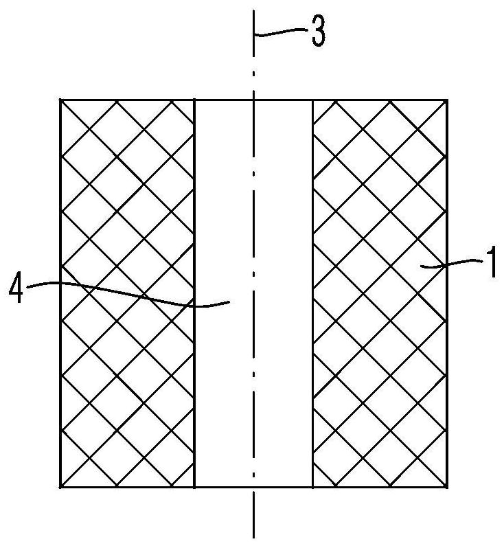
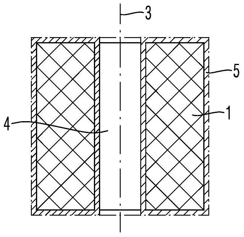
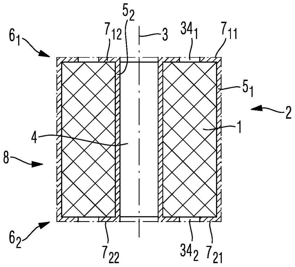
[0120] In the following, reference will be made to Figures 1A to 1C The principle of the method for producing a high-frequency connector according to the invention is explained:

[0121] exist Figure 1A In the first manufacturing step shown, the base part 1 of the high-frequency connector 2 according to the invention is produced from a dielectric material. The base part 1 has a single sleeve 4 extending along a longitudinal axis 3 . The geometry of the dielectric matrix part 1 need not necessarily be a hollow cylinder, for simplicity as Figures 1A to 1C shown. Other geometries than the hollow cylindrical geometry of the base part 1 are also conceivable, eg for high-frequency right-angle connectors.

[0122] Preferably, in order to achieve the concentricity between the inner conductor coating and the outer conductor coating of the high frequency connector 2 of the present invention, the geometry of the base part 1 is formed to be rotationally symmetrical with respect to t...


PUM


Abstract

The present invention relates to a method for manufacturing a high-frequency connector. The method involves manufacturing a main body part from a dielectric material by means of an additive manufacturing method. The main body part has a passage between a first end and a second end of the longitudinal extension of the main body part, and has an end face on the first end for contacting a mating connector. In addition, the method involves coating the dielectric main body part with an electrically conductive layer, and removing the electrically conductive layer in a region surrounding the passageon the end face at each of the first and second ends of the main body part, in order to form an electrically conductive coating on the side of the outer conductor, and an electrically conductive coating on the side of the inner conductor. The present invention further relates to a high-frequency connector.

Description

technical field [0001] The present invention relates to a method and related apparatus for producing high frequency connectors. Background technique [0002] An electrical connection between a cable and another cable is made and released again by a pair comprising an interconnectable connector and an associated mating connector. [0003] Such a connector can also be realized between the cable and the printed circuit board or between the cable and the housing of the electronic assembly. In each case, a connector can also be realized between two printed circuit boards or between a printed circuit board and a housing of a printed circuit board or between the housings of two electronic components. [0004] Such a connector enables an electrical connection not only for one or more DC voltage signals or low-frequency signals, but also for one or more high-frequency signals. Here and in the following, a high-frequency signal is understood to mean a signal with a frequency above 3...

Claims


Application Information

Patent Timeline
Patent Type & Authority Applications(China)
IPC IPC(8): H01R43/16H01R13/03H01R13/6476H01R12/70H01R13/24H01R24/50
CPCH01R12/714H01R12/73H01R13/035H01R13/2421H01R13/2442H01R13/2485H01R13/2492H01R13/6476H01R24/50H01R43/007H01R43/16H01R13/2414
Inventor 弗兰克·塔特泽伊豪克﹒舒特亚历山德拉﹒亨尼尔路德维希
Owner ROSENBERGER HOCHFREQUENZTECHNIK GMBH & CO KG
Features
  • R&D
  • Intellectual Property
  • Life Sciences
  • Materials
  • Tech Scout
  • Unparalleled Data Quality
  • Higher Quality Content
  • 60% Fewer Hallucinations
Learn More