Supercharge Your Innovation With Domain-Expert AI Agents!

Foam molding machine

A molding machine and foam technology, applied in the field of foam molding, can solve the problems of large mold volume, inconvenient installation, maintenance and replacement of fixed molds, and bulkiness

Pending Publication Date: 2020-10-30
温州市珍发机械有限公司
View PDF0 Cites 0 Cited by
  • Summary
  • Abstract
  • Description
  • Claims
  • Application Information

AI Technical Summary

Problems solved by technology

[0004] The purpose of the present invention is to provide a foam molding machine to solve the problem of the existing foam molding machine due to the large and heavy mold, and each time the mold is replaced, the demoulding bottom plate and the demoulding pull rod must be replaced accordingly to adapt to different molds. The thickness of the mold, the installation, maintenance and replacement of a given mold have brought great inconvenience

Method used


Image

  • Foam molding machine
  • Foam molding machine
  • Foam molding machine

Examples


Embodiment Construction

[0025] The specific implementation manners of the present invention will be further described in detail below in conjunction with the accompanying drawings and embodiments. The following examples are used to illustrate the present invention, but are not intended to limit the scope of the present invention.

[0026] In the description of the present invention, it should be understood that the orientations or positional relationships indicated by the terms "upper", "lower", "left", "right", "top", "bottom" etc. are based on those shown in the drawings. Orientation or positional relationship is only for the convenience of describing the present invention and simplifying the description, and does not indicate or imply that the referred device or element must have a specific orientation, be constructed and operated in a specific orientation, and thus should not be construed as a limitation of the present invention.

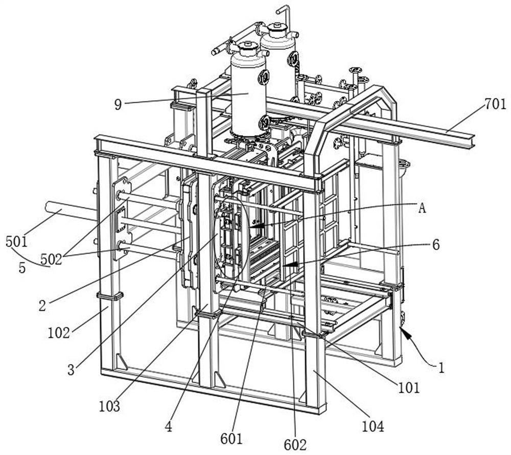
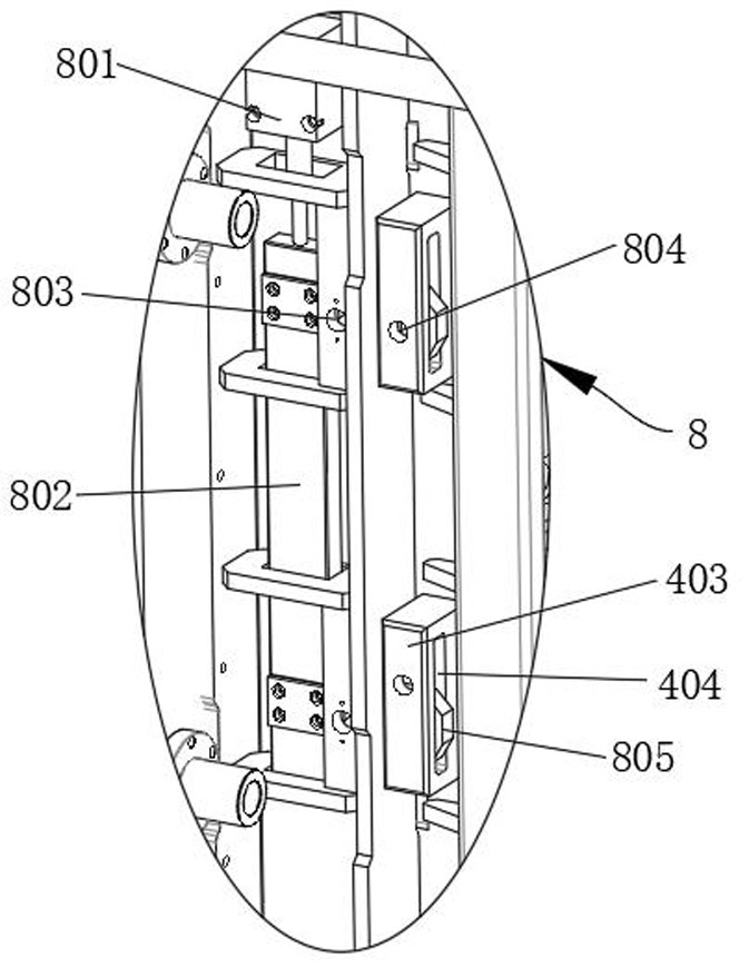
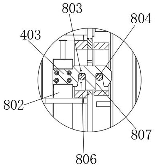
[0027] combine Figures 1~9 As shown, a foam molding machine acc...


PUM


Abstract

The invention relates to the technical field of foam molding and discloses a foam molding machine. The foam molding machine comprises a rack as well as a moving mold frame, a fixed mold frame, a movable mold frame, a mold assembly driving mechanism, a demolding mechanism and a translation mechanism which are arranged on the rack, wherein the mold assembly driving mechanism is used for driving themoving mold frame to be close to or far away from the fixed mold frame; the demolding mechanism is used for product demolding; and the translation mechanism is used for driving the movable mold frameto be close to or far away from the fixed mold frame. Specifically, a quick locking mechanism is unlocked when the mold replacement operation is needed, so that the movable mold frame can be driven bythe translation mechanism to be separated from the fixed mold frame along guiding rails, thereby achieving the dismounting and replacement of a fixed mold; through the arrangement of rollers matchedwith the guiding rails at the bottom of the movable mold frame, the dismounting and mounting of the movable mold frame can be further facilitated, thereby saving time and effort; furthermore, first connecting holes formed in a connecting cross beam of a demolding baseplate can be selectively connected with different second connecting holes, thereby adapting to and being matched with fixed molds ofdifferent thicknesses; and consequently, a proper demolding space can always be left between the demolding baseplate and the fixed mold.

Description

technical field [0001] The invention relates to the technical field of foam molding, in particular to a foam molding machine. Background technique [0002] The foam forming machine is a relatively mature equipment, which is used to fill the foam particles into the mold, and perform steam heating and pressure to form the foam box. [0003] The fixed mold of the existing foam molding machine is sent to the fixed mold frame by a forklift or other special conveying mechanism, and then manually installed. Due to the large size and heavy weight of the mold, the installation and maintenance of the fixed mold And the replacement has brought great inconvenience; further, in order to better realize the demoulding, it is necessary to maintain the relative demoulding distance between the demoulding bottom plate and the fixed mold, but because different products need to replace different molds, The thickness of different molds is different, so that every time the mold is changed, the de...

Claims


Application Information

Patent Timeline
IPC IPC(8): B29C44/34B29C33/30
CPCB29C33/30B29C33/306B29C44/34
Inventor 李珍发张从全
Owner 温州市珍发机械有限公司
Features
  • R&D
  • Intellectual Property
  • Life Sciences
  • Materials
  • Tech Scout
  • Unparalleled Data Quality
  • Higher Quality Content
  • 60% Fewer Hallucinations
Learn More