Check patentability & draft patents in minutes with Patsnap Eureka AI!

A rotary electroplating mechanical cantilever conductive mechanism

A rotary, rotating mechanism technology, used in current conducting devices, electrolysis components, electrolysis processes, etc., can solve the problems of high temperature softening of insulating skins, damage to insulating skins, etc.

Active Publication Date: 2021-08-17
义乌市义心科技有限责任公司
View PDF8 Cites 0 Cited by
  • Summary
  • Abstract
  • Description
  • Claims
  • Application Information

AI Technical Summary

Problems solved by technology

[0003] Since the clamping head of the front end of the rotary electroplating mechanical cantilever can rotate greatly, and when the clamping head rotates, it will drive the conductive wire connected to it to rotate synchronously. If the clamping head rotates 360°, the internal conductive wire will also rotate The corresponding rotation is tightened, and the outer insulation of the conductive wire will soften at high temperature after long-term use, which will easily cause the outer insulation of the conductive wire to be damaged under repeated tightening.

Method used


Image

  • A rotary electroplating mechanical cantilever conductive mechanism
  • A rotary electroplating mechanical cantilever conductive mechanism
  • A rotary electroplating mechanical cantilever conductive mechanism

Examples


Embodiment 1

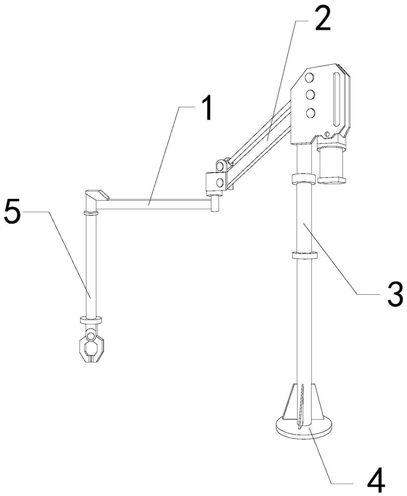
[0026] For example figure 1 -example Figure 5 Shown:

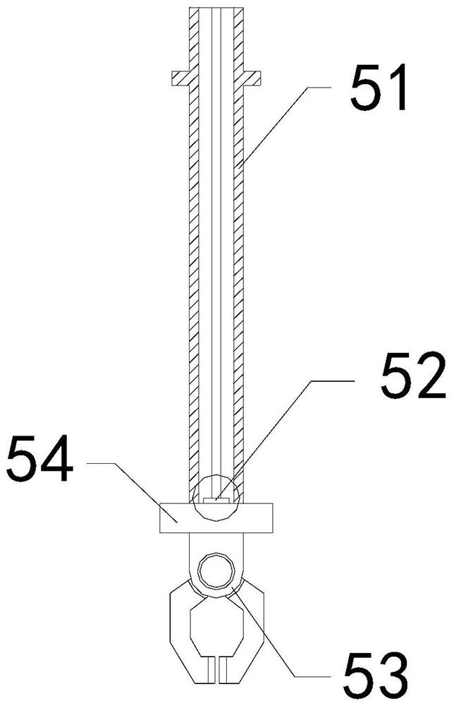
[0027] The invention provides a cantilever conductive mechanism of a rotary electroplating machine, the structure of which includes a middle connecting rod 1, an engaging arm 2, a support rod 3, a base 4, and a clamping mechanism 5, and the middle connecting rod 1 and the connecting arm 2 are movably engaged. , the connecting arm 2 is connected to the upper end of the support rod 3, the support rod 3 is welded to the base 4, the clamping mechanism 5 is installed at the front end of the connecting rod 1; the clamping mechanism 5 includes an outer Frame 51, conductive mechanism 52, clamping head 53, rotating disk 54, the outer frame 51 is connected with the rotating disk 54, the conductive mechanism 52 is embedded in the upper end position of the rotating disk 54, and the clamping head 53 is installed At the bottom position of the rotating disk 54.

[0028] Wherein, the conductive mechanism 52 includes a heat conduction ...

Embodiment 2

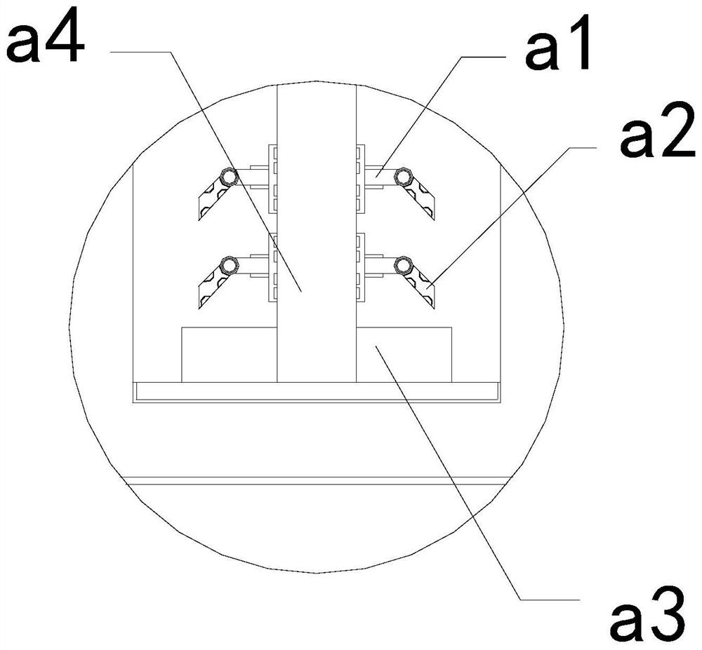
[0034] For example Figure 6 -example Figure 8 Shown:

[0035] Wherein, the wire fixing ring a35 includes a fixed block c1, a booster bar c2, an overhanging frame c3, and an outer ring c4, the fixed block c1 and the outer ring c4 are an integrated structure, and the booster bar c2 is installed Between the block c1 and the outrigger c3, the outrigger c3 is movably engaged with the inner position of the fixed block c1 and the outer ring c4, and there are six outriggers c3, which are evenly placed on the outer ring c4 Distributed in a circular shape, through the thrust generated by the booster bar c2 on the outrigger c3, the outrigger c3 can fix the position of the conductive wire.

[0036] Wherein, the outstretched frame c3 includes a plate body c31, an elastic piece c32, an inner clamping block c33, a transmission line c34, and a linkage rod c35, and the elastic piece c32 is installed between the plate body c31 and the inner clamping block c33. The inner clamping block c33 ...


PUM


Abstract

The invention discloses a cantilever conductive mechanism of a rotary electroplating machine. The support rod is welded to the base, and the clamping mechanism is installed at the front end of the intermediate rod. The clamping head is driven to rotate by the rotating disc, so that the outer disc can follow the rotating disc to rotate, and when the outer disc rotates, the force-bearing block The resulting extrusion can shrink the force-bearing block inward, so that the integrated disk cannot rotate synchronously with the rotation of the outer disk, so that the conductive wire installed in the middle of the wire fixing ring will not rotate and tighten, and the external extension frame will be generated by the booster bar. The thrust can make the outrigger frame protrude outward along the outer ring, so that the protruding outrigger can clamp the conductive wire, effectively avoiding that the diameter of the wire fixing ring cannot be changed, which will make the wire fixing ring Cannot accommodate smaller diameter conductive wires.

Description

technical field [0001] The invention relates to the field of electroplating, in particular to a cantilever conductive mechanism of a rotary electroplating machine. Background technique [0002] The conductive mechanism of the rotary electroplating mechanical cantilever is mainly used to provide power support for the rotary electroplating mechanical cantilever. It usually runs through the internal position of the rotary electroplating mechanical cantilever and guides the current to each electrical appliance on the rotary electroplating mechanical cantilever. , so as to realize the normal operation of the rotary electroplating mechanical cantilever. Based on the above description, the inventors found that the existing conductive mechanism of a rotary electroplating mechanical cantilever mainly has the following deficiencies, for example: [0003] Since the clamping head of the front end of the rotary electroplating mechanical cantilever can rotate greatly, and when the clampin...

Claims


Application Information

Patent Timeline
Patent Type & Authority Patents(China)
IPC IPC(8): C25D17/00
CPCC25D17/007
Inventor 尤德逢
Owner 义乌市义心科技有限责任公司
Features
  • R&D
  • Intellectual Property
  • Life Sciences
  • Materials
  • Tech Scout
  • Unparalleled Data Quality
  • Higher Quality Content
  • 60% Fewer Hallucinations
Learn More