
Buttress for prefabricated assembly type energy dissipater and connecting joint between buttress and energy dissipater

A technology of connecting nodes and prefabricated assembly, which is applied in the direction of protective buildings/shelters, building types, buildings, etc., and can solve the problems of long time consumption and many installation steps of energy absorbers

Pending Publication Date: 2020-10-30
GUANGZHOU UNIVERSITY
View PDF0 Cites 4 Cited by
  • Summary
  • Abstract
  • Description
  • Claims
  • Application Information

AI Technical Summary

Problems solved by technology

[0005] The purpose of the present invention is to provide a connection node between the pier and the energy dissipator to solve the problem that the energy dissipating pier and the energy dissipator in the prior art are installed by on-site pouring, and the installation of the energy dissipator requires many steps and takes a long time problem; the present invention also provides a prefabricated assembly type energy dissipation device with buttresses

Method used


Image

  • Buttress for prefabricated assembly type energy dissipater and connecting joint between buttress and energy dissipater
  • Buttress for prefabricated assembly type energy dissipater and connecting joint between buttress and energy dissipater
  • Buttress for prefabricated assembly type energy dissipater and connecting joint between buttress and energy dissipater

Examples


Embodiment Construction

[0029] The specific implementation manners of the present invention will be further described in detail below in conjunction with the accompanying drawings and embodiments. The following examples are used to illustrate the present invention, but are not intended to limit the scope of the present invention.

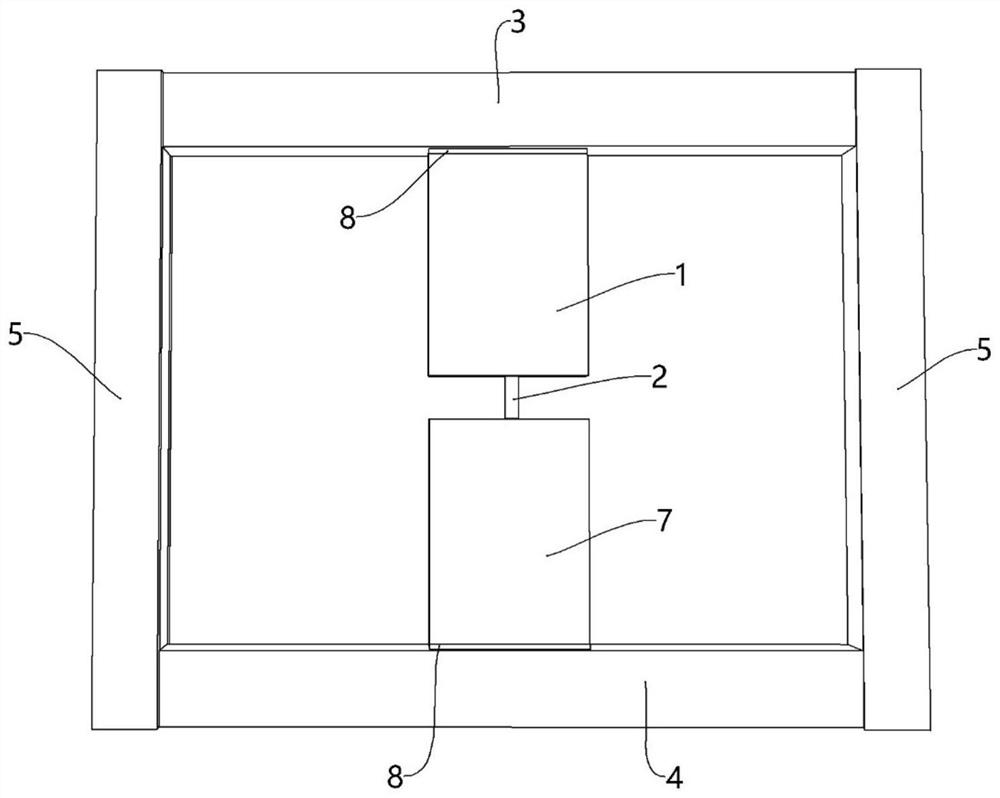
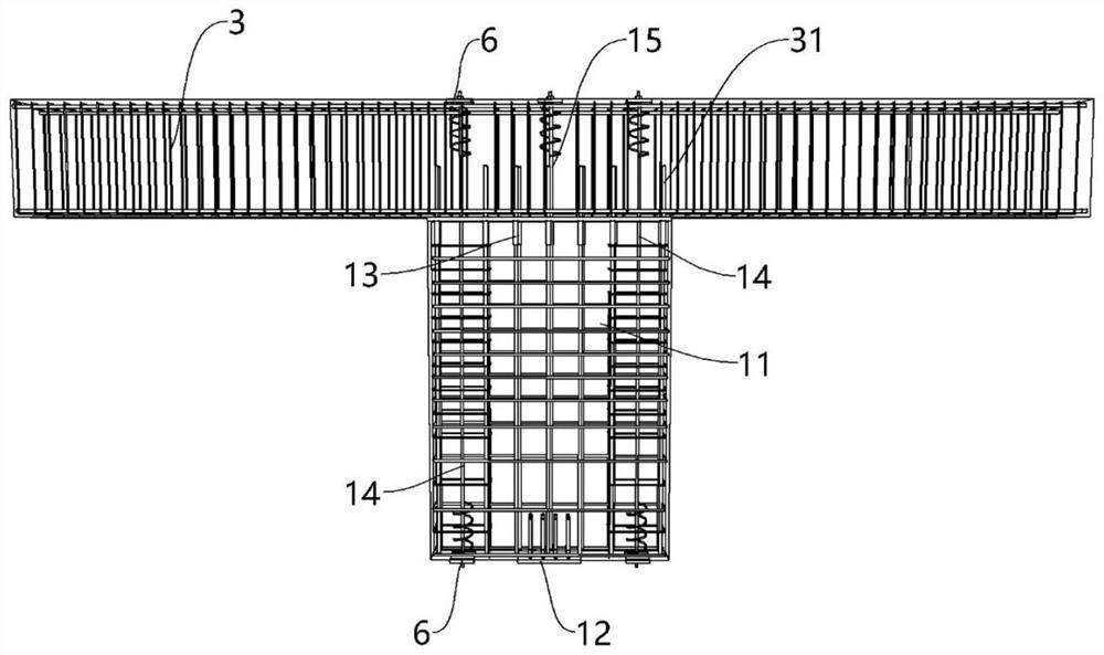
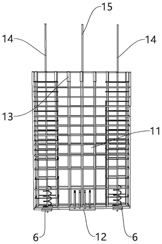
[0030] A preferred embodiment of the connection node between the pier and the energy dissipator of the present invention, such as Figure 1 to Figure 11 As shown, the connection node between the pier and the energy dissipator includes the pier, the energy dissipator 2, the connecting beam, the frame column 5, the anchor assembly 6 and the prestressed tendons 14, and the energy dissipator 2 includes the energy dissipating section 21 and the connecting plate 22 , the energy dissipating section 21 is the main structure used for dissipating vibration energy in the energy dissipating device 2, the connecting plate 22 is a rectangular plate structure, there are two connecting pl...


PUM


Abstract

The invention relates to the technical field of energy dissipation and shock absorption, and discloses a buttress for a prefabricated assembly type energy dissipater and a connecting joint between thebuttress and the energy dissipater. The connecting joint between the buttress and the energy dissipater comprises the energy dissipater and two buttresses connected with the energy dissipater, the energy dissipater comprises an energy dissipation section and connecting plates arranged at the two ends of the energy dissipation section correspondingly, the two buttresses are arranged on the upper side and the lower side of the energy dissipater correspondingly, the buttresses comprise buttress bodies and connecting assemblies arranged on the buttress bodies, the connecting assemblies are arranged on the buttress bodies in an embedded mode, and the connecting plates at the two ends of the energy dissipater are connected with the connecting assemblies of the two buttresses correspondingly. Due to the fact that the connecting assemblies are arranged on the buttress bodies of the buttresses in the embedded mode, when the energy dissipater is assembled, constructors can prefabricate and formthe connecting assemblies and the buttress bodies in a workshop, only the energy dissipater needs to be connected with the connecting assemblies on site, the buttresses do not need to be poured on site, and therefore installation steps of the energy dissipater are reduced, and installation time of the energy dissipater is shortened.

Description

technical field [0001] The invention relates to the technical field of energy dissipation and shock absorption, in particular to a support pier for a prefabricated energy dissipation device and a connection node between the support pier and the energy dissipation device. Background technique [0002] As green buildings and industrialized buildings become the future trend, prefabricated buildings will gradually develop. However, due to various factors, my country's prefabricated buildings have weaker seismic performance than cast-in-place structures, which limits the development of prefabricated buildings. , the use of energy dissipation and shock absorption technology is expected to help prefabricated structures solve current problems. [0003] Effective shock absorption technologies mainly include damper support and pier-type connection, etc. Compared with damper support, buttress-type connection has the following advantages: ①It does not affect the building function too muc...

Claims


Application Information

Patent Timeline
IPC IPC(8): E04B1/98E04H9/02E04B1/38E04B1/41E04G21/00
CPCE04B1/98E04H9/02E04B1/38E04B1/41E04G21/00
Inventor 张超周云林容粤
Owner GUANGZHOU UNIVERSITY
Learn More