Airplane wheel brake torque testing device
A testing device and braking force technology, which is applied in measuring devices, aircraft component testing, force/torque/power measuring instruments, etc., can solve problems such as inaccurate torque results, time-consuming and labor-intensive problems, and achieve easy operation and ensure accuracy , the effect of reducing the impact
- Summary
- Abstract
- Description
- Claims
- Application Information
AI Technical Summary
Problems solved by technology
Method used
Image

Examples
Example Embodiment
[0027] Example 1:
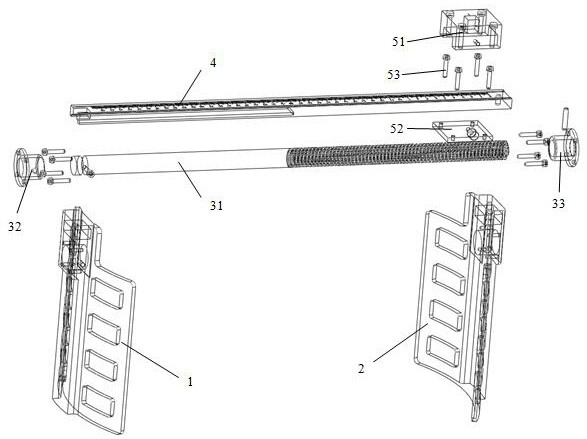
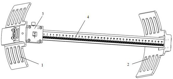
[0028] A wheel brake torque test device of this embodiment, such as Figure 1-Figure 4 As shown, it includes a left splint 1 and a right splint 2 arranged on the left and right. The left splint 1 and the right splint 2 are connected by a moving assembly 3, and the moving assembly 3 is used to drive the left splint 1 and the right splint 2 to approach each other or Far away from each other; parallel to one side of the moving component 3 is provided with a ruler 4 that moves in the opposite direction to the moving component 3 and is used to detect the distance between the left splint 1 and the right splint 2, and a test component 5 is slidably arranged on the ruler 4, The test assembly 5 is provided with a test port for testing torque.
[0029] The left splint 1 and the right splint 2 are respectively arranged on the left and right sides of the wheel. The left splint 1 and the right splint 2 approach each other under the driving of the moving assembly 3 until the...
Example Embodiment
[0030] Example 2:
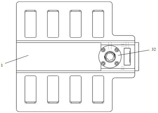
[0031] This embodiment is further optimized on the basis of embodiment 1, such as figure 1 As shown, the moving assembly 3 includes a screw rod 31, a coaxially arranged left insert 32 and a right insert 33. The left insert 32 is arranged on the top of the left splint 1, and the right insert 33 is arranged on the right. On the top of the splint 2, the left end of the screw rod 31 is rotatably clamped with the left insert 32, and the right end of the screw rod 31 is threadedly connected with the right insert 33.
[0032] The tops of the left splint 1 and the right splint 2 are coaxially provided with a left mounting hole and a right. The left insert 32 is installed in the left mounting hole on the top of the left splint 1, and the right insert 33 is installed on the top of the right splint 2. In the hole, the left end of the left insert 32 corresponds to the left end of the left mounting hole with a left flange, and the left flange and the left end of the left mou...
Example Embodiment
[0037] Example 3:
[0038] This embodiment is further optimized on the basis of the above-mentioned embodiment 1 or 2, in order to avoid the difference between the cross-sectional area of the screw 31 and the cross-sectional area of the ruler 4 being too large, resulting in the relative linear movement of the screw 31 and the ruler 4 The unbalanced moment, therefore, the cross-sectional area of the screw rod 31 is equal to the cross-sectional area of the scale 4, and the unbalanced moment generated when the screw rod 31 and the scale 4 move relatively linearly is minimized.
[0039] Further, the left side of the midpoint of the screw rod 31 is an optical axis section, the right side of the midpoint of the screw rod 31 is a threaded section, and the optical axis section of the screw rod 31 is rotatably connected with the installation light hole inside the left insert 32, The threaded end of the screw rod 31 is threadedly connected with the mounting threaded hole inside the r...
PUM
 Abstract
Description
Claims
Application Information
 - R&D Engineer
- R&D Manager
- IP Professional
- Industry Leading Data Capabilities
- Powerful AI technology
- Patent DNA Extraction
Browse by: Latest US Patents, China's latest patents, Technical Efficacy Thesaurus, Application Domain, Technology Topic.
© 2024 PatSnap. All rights reserved.Legal|Privacy policy|Modern Slavery Act Transparency Statement|Sitemap