Paint spraying device with pre-drying function
A functional and pre-baking technology, which is applied in the direction of spraying devices, devices for coating liquid on the surface, spray booths, etc., can solve the problems of difficult cleaning of baffles, lack of anti-paint mist measures, and easy damage to paint surfaces, and achieve reduction Contamination, avoid curing spray tubes, achieve the effect of heat accumulation
- Summary
- Abstract
- Description
- Claims
- Application Information
AI Technical Summary
Problems solved by technology
Method used
Image


Examples
Embodiment
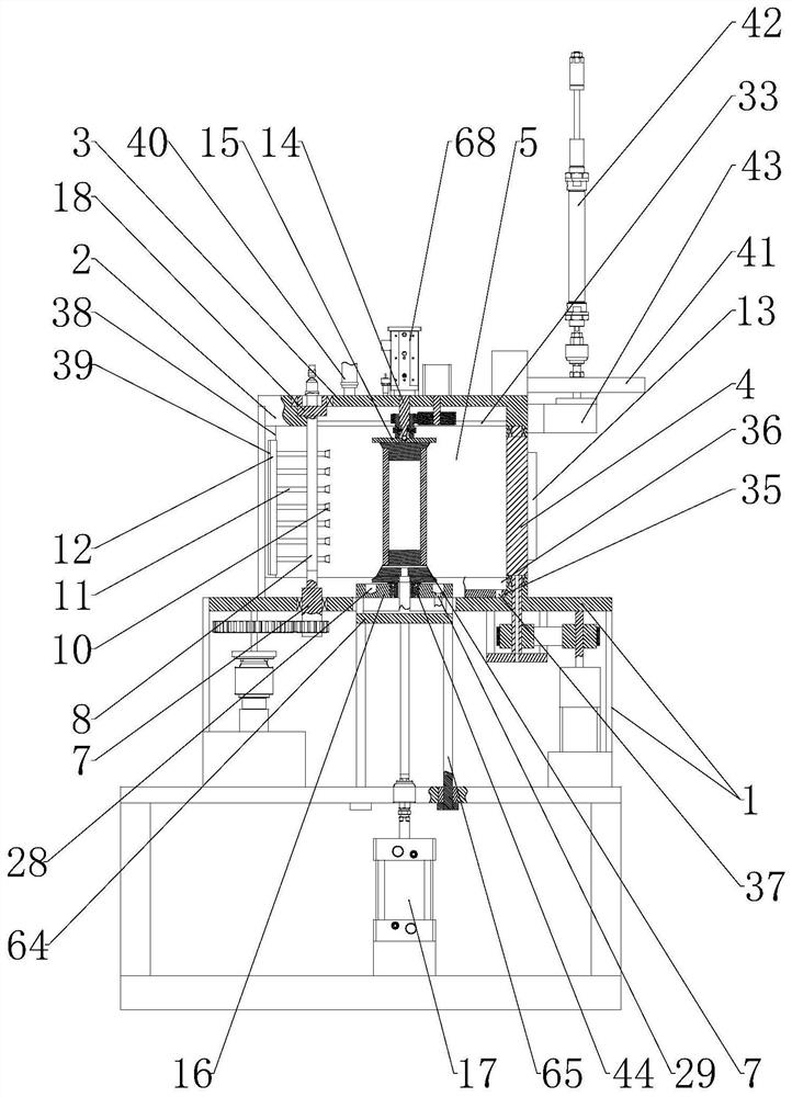
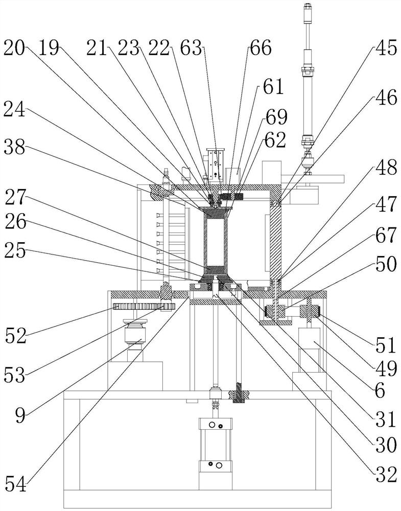
[0058] see Figure 1-7 , a paint spraying device with a pre-baking function, including a support base 1;
[0059] A support frame 2 is installed on the support base 1, a top plate 3 is installed on the top of the support frame 2, a mounting plate 4 is installed on the front end of the support frame 2, and side baffles 5 are installed on both sides of the support frame 2. The rear end is provided with an opening, and a mounting plate driving device for driving the mounting plate 4 to rotate is installed on the support base 1;
[0060] The rear end of the mounting plate 4 is arranged on a smooth surface, and the front end of the mounting plate 4 is equipped with a paint-baking lamp 13;
[0061] On the top plate 3, an upper clamp support rod 14 is installed, and the bottom end of the upper clamp support rod 14 is rotatably connected with an upper clamp 15, and an upper clamp driving device for driving the upper clamp 15 to rotate is also installed on the top plate 3; A lower cl...
Embodiment 2
[0073] This embodiment is further defined as follows on the basis of Embodiment 1: the lower end of the upper clamp support rod 14 is provided with an annular sliding groove 23;
[0074] The upper clamp 15 has a connecting sleeve section 19 that can be sleeved on the lower end of the upper clamp support rod 14, and the bottom end of the connecting sleeve section 19 is connected with an upper clamping blocking plate 20;
[0075] It also includes a clamping limiter 21 that runs through the side wall of the connecting sleeve segment 19 and is threadedly engaged with the connecting sleeve segment 19, and the clamping limiter 21 is located in the area covered by the annular sliding groove 23;
[0076] The upper clamp elastic part 22 is also arranged in the annular sliding groove 23, and the upper and lower ends of the upper clamp elastic part 22 respectively abut against the inner wall surface of the annular sliding groove 23 and the top end of the clamping limiter 21, so that: clam...
Embodiment 3
[0088] This embodiment makes the following further limitations on the basis of Embodiment 1: side water pipes 33 are installed on the left and right sides of the bottom of the top plate 3, and several side water branch pipes 34 are connected to the side water pipes 33. The output end of the side water branch pipe 34 on the side water pipe 33 can respectively act on the upper ends of the two side baffles 5;
[0089] The lower ends of both side baffle plates 5 are connected with a side waste paint collection seat 35, and the top of the side waste paint collection seat 35 is provided with a side waste paint collection tank 36, and the side waste paint collection seat 35 is also provided with a side waste paint collection seat 35. The side waste paint collecting connection port 37 communicated with the groove 36 .
[0090] Preferably, an exhaust pipe 40 is also installed on the top plate 3 . The exhaust pipe 40 is communicated with an exhaust fan.
PUM
 Abstract
Description
Claims
Application Information
 - R&D
- Intellectual Property
- Life Sciences
- Materials
- Tech Scout
- Unparalleled Data Quality
- Higher Quality Content
- 60% Fewer Hallucinations
Browse by: Latest US Patents, China's latest patents, Technical Efficacy Thesaurus, Application Domain, Technology Topic, Popular Technical Reports.
© 2025 PatSnap. All rights reserved.Legal|Privacy policy|Modern Slavery Act Transparency Statement|Sitemap|About US| Contact US: help@patsnap.com