Check patentability & draft patents in minutes with Patsnap Eureka AI!

Array system synchronous measurement and control network architecture

A measurement and control network and array technology, which is applied in the field of synchronous measurement and control network architecture of the array system, can solve problems such as difficulty in handling faulty equipment, weak anti-interference ability, and inability to realize the synchronous control function and real-time control function of the array system. Effects of anti-interference ability, performance improvement and complexity reduction

Active Publication Date: 2020-11-03
INST OF ELECTRICAL ENG CHINESE ACAD OF SCI
View PDF3 Cites 0 Cited by
  • Summary
  • Abstract
  • Description
  • Claims
  • Application Information

AI Technical Summary

Problems solved by technology

[0004] The purpose of the present invention is to overcome the shortcomings of the existing measurement and control network that cannot realize the synchronous control function and real-time control function of the array system, the difficulty in handling faulty equipment, and the weak anti-interference ability, and propose a synchronous measurement and control network architecture of the array system. The present invention realizes The synchronous control and real-time control functions of the array system reduce the difficulty of software development and improve the reliability of communication

Method used


Image

  • Array system synchronous measurement and control network architecture
  • Array system synchronous measurement and control network architecture
  • Array system synchronous measurement and control network architecture

Examples


Embodiment Construction

[0019] The present invention will be further described below in conjunction with the accompanying drawings and specific implementation examples.

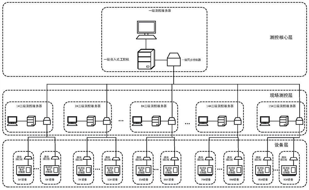
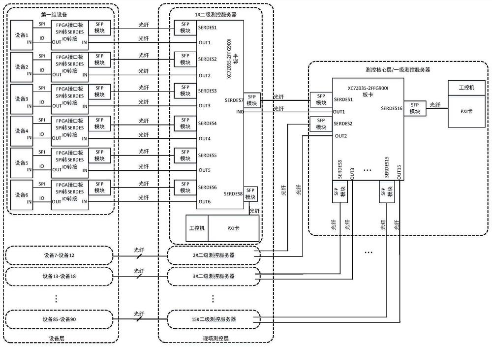
[0020] figure 2 Shown is a schematic diagram of the synchronous measurement and control network architecture of the array pulse generator control system according to the embodiment of the present invention. Such as figure 2 As shown, the device layer of the synchronous measurement and control network is composed of multiple array pulse generator controllers and communication interface boards. Each pulse generator controller is matched with a communication interface board, and a pulse generator controller and a communication interface board form a device, that is, the measurement and control object. Group devices according to actual needs. The synchronous measurement and control network is designed to control the functions of reliable synchronous high-current and high-voltage pulse discharge, collection and transfer of surplus e...


PUM


Abstract

An array type system synchronous measurement and control network architecture is a tree type network architecture and comprises three levels: a measurement and control core layer which is far away from a measurement and control object and is composed of a first-level measurement and control server, a field control layer which is close to the measurement and control object and is composed of a plurality of second-level measurement and control servers, and an equipment layer, wherein the measurement and control object is composed of an array type system. The three levels respectively correspondto tree roots, sub-tree roots and leaf nodes in a tree-type network structure. And the three levels are cascaded with a signal synchronization network through a data synchronization network based on optical fiber communication. A primary measurement and control server is connected with all secondary measurement and control servers through a plurality of SERDES buses which are mutually independent,and each secondary measurement and control server is connected with corresponding equipment through a plurality of SERDES buses which are mutually independent, so that a data synchronization networkis formed. The first-level measurement and control server outputs homologous IO signals to all the second-level measurement and control servers, and the second-level measurement and control servers output homologous IO signals to all the devices corresponding to the second-level measurement and control servers, so a signal synchronization network is formed.

Description

technical field [0001] The invention relates to an array system synchronous measurement and control network architecture. Background technique [0002] In the electromagnetic ejection system, an array-type pulse generator set is used to provide high-power pulses to realize the instantaneous high-voltage and high-current discharge required for electromagnetic ejection. The pulsed high voltage and high current bring strong electromagnetic interference. How to reliably control the synchronous operation of the arrayed pulsed generators, process the operating data of the arrayed pulsed generators in parallel in real time, and realize the instantaneous discharge of the maximum capacity of all generators at the same time. Or the realization of separate control of different generator sets for instantaneous discharge sequence, or the realization of the function of collecting and redistributing the remaining electricity is the key to the successful launch of the electromagnetic catapu...

Claims


Application Information

Patent Timeline
Patent Type & Authority Applications(China)
IPC IPC(8): H04J3/06H04Q11/00
CPCH04J3/0638H04J3/0658H04Q11/0062H04Q2011/0081Y02P90/02
Inventor 颜朝鹏张剑温旭辉
Owner INST OF ELECTRICAL ENG CHINESE ACAD OF SCI
Features
  • R&D
  • Intellectual Property
  • Life Sciences
  • Materials
  • Tech Scout
  • Unparalleled Data Quality
  • Higher Quality Content
  • 60% Fewer Hallucinations
Learn More