Dialysis tube fixation device for nephrology department

A technology of fixing device and dialysis tube, applied in dialysis system, peritoneal dialysis, catheter and other directions, can solve the problems of dialysis tube bending, unfavorable peritoneal dialysis treatment, etc., to ensure smooth input and ensure the effect of treatment effect

Inactive Publication Date: 2020-11-06
周宗祥
View PDF0 Cites 2 Cited by
  • Summary
  • Abstract
  • Description
  • Claims
  • Application Information

AI Technical Summary

Problems solved by technology

[0005] Aiming at the deficiencies of the prior art, the present invention provides a dialysis tube fixation device for nephrology, which solves the problem that the dialysis tube fixation device of the prior art, due to the dragging of the different body positions of the patient, is stuck on the edge of the existing clamping cavity. Dialysis tubing is often bent, which is not conducive to the treatment of peritoneal dialysis

Method used


Image

  • Dialysis tube fixation device for nephrology department
  • Dialysis tube fixation device for nephrology department
  • Dialysis tube fixation device for nephrology department

Examples


Embodiment

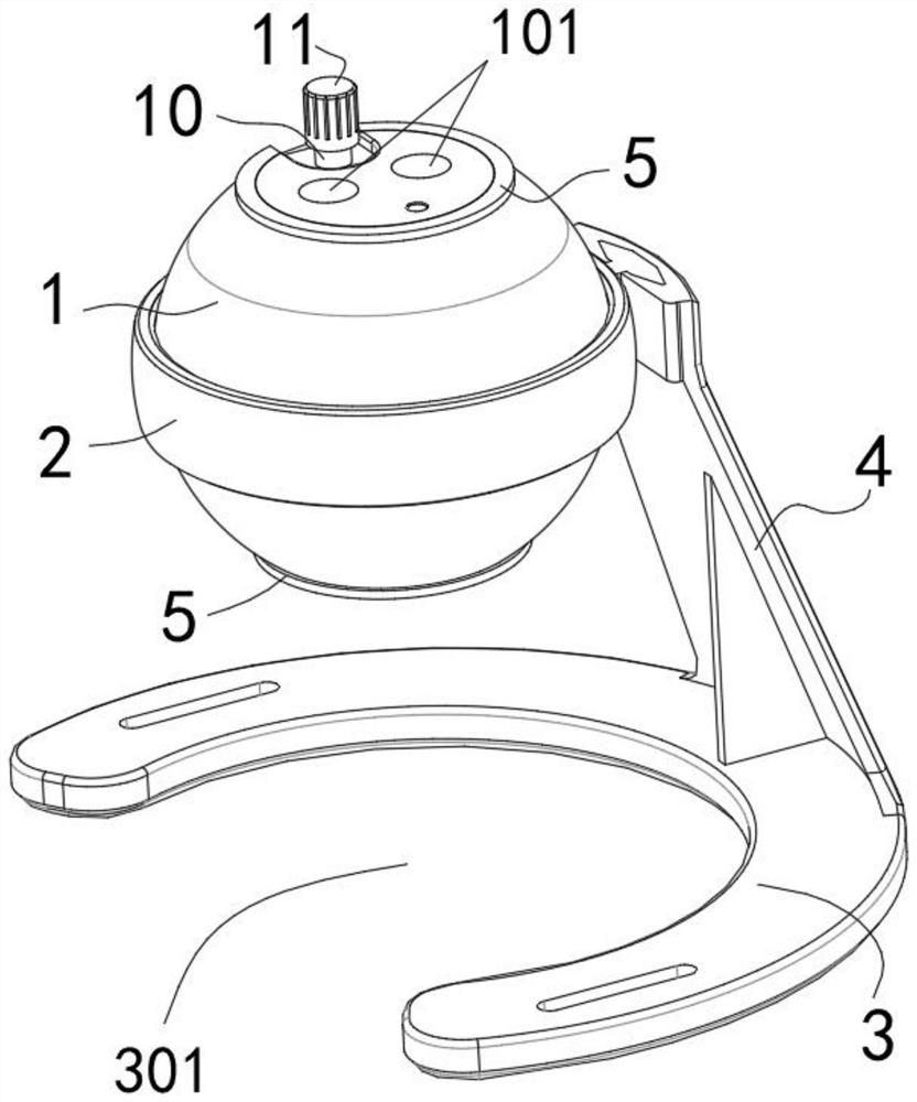
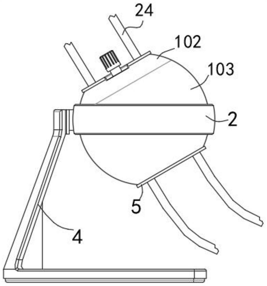
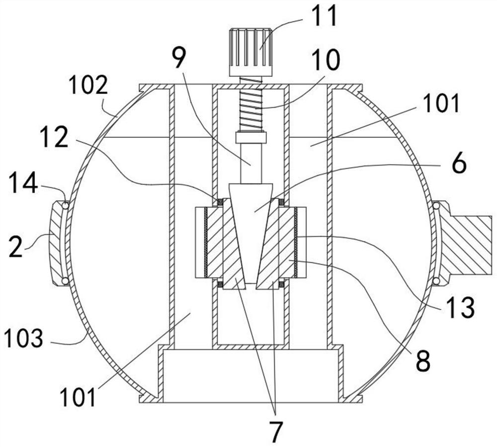
[0032] A kind of dialysis tubing fixing device for nephrology department of the present embodiment, refer to figure 1 , including the fixed body 1, the main body surface of the fixed body 1 is a spherical surface, a set of jacks 101 are provided through the top of the fixed body 1 downwards, and a clamping structure is arranged inside the jacks 101; spherical ring body 2, 2 sets of spherical ring bodies Set outside the main body of the fixed body 1, the fixed body 1 can rotate inside the spherical ring body 2; the support body, the support body includes a base 3 and a support rod 4, the support rod 4 is fixed on the base 3, and the spherical ring body 2 is detachable Fixed on the support rod 4, the fixed body 1 is located directly above the base 3, and the orthographic projection area of ​​the fixed body 1 on the base 3 is provided with a gap 301, (the gap 301 is reserved for the convenience of fixing the device on the patient's abdomen. , reserve the space for inserting the d...

Embodiment 2

[0044] The difference from that described in the first embodiment above is that referring to Figure 7 In this implementation, 3M adhesive stickers 20 are provided at the bottom of the base 3, and the base 3 of the support is glued and fixed on the edge of the hospital bed 21 during use, thereby reducing the restraint on the patient's abdomen.


PUM

PropertyMeasurementUnit
Outer diameteraaaaaaaaaa

Abstract

The invention relates to the technical field of medical assisted devices, and provides a dialysis tube fixation device for the nephrology department. The dialysis tube fixation device for the nephrology department comprises a fixation body, a ball ring body and a support body; the main body surface of the fixation body is a spherical surface; the top of the fixation body is provided with a set ofinsertion holes in a downward penetrating manner; a clamping structure is arranged at the inner side of the insertion hole; the ball ring body is arranged outside the main body of the fixation body ina sleeving manner; the fixation body can rotate at the inner side of the ball ring body; the support body comprises a base and a support rod; the support rod is fixed on the base; the ball ring bodyis detachably fixed on the support rod; the fixation body is right above the base; a nick is arranged in the orthographic projection area of the fixation body on the base, wherein protrusion limitingbodies are arranged at the edges of the top and the bottom of the fixation body; and the limiting bodies are used for limiting the rotation angle of the fixation body in the ball ring body. The dialysis tube fixation device for the nephrology department in the invention solves the following problems of the dialysis tube fixation device in the prior art: because of dragging of patients in differentpositions, the dialysis tube bending phenomenon often occurs at the edge of the existing clamping cavity; and the device is not good for treatment of peritoneal dialysis.

Description

technical field [0001] The invention relates to the technical field of medical auxiliary devices, in particular to a dialysis tube fixing device for nephrology. Background technique [0002] Peritoneal dialysis needs to place a peritoneal dialysis tube in the abdominal cavity of the human body. The outer end of the peritoneal dialysis tube is exposed to the abdominal wall of the human body and is used to communicate with the outer tube or peritoneal dialysis fluid. The peritoneal dialysis tube needs 3-4 times a day Connect the external tube to the ground for dialysis operations. The operation is relatively frequent, and the peritoneal dialysis tube will often be pulled. Therefore, in order to protect the peritoneal dialysis tube from shifting, medical staff generally wear a peritoneal dialysis tube support bag on the patient's waist and abdomen. or other girdles. However, when the abdominal bag is used, there are still many deficiencies. For example, the ordinary abdominal ...

Claims


Application Information

Patent Timeline
IPC IPC(8): A61M1/28A61M25/02A61G7/05
CPCA61G7/05A61G2210/20A61M1/285A61M25/02A61M2025/028
Inventor 周宗祥
Owner 周宗祥
Why Eureka
Try Eureka