Arc extinguishing chamber structure of circuit breaker
A technology of arc extinguishing chamber and circuit breaker, which is applied in the direction of circuit breaker components, etc. It can solve the problems that the arc is difficult to achieve segmentation, insufficient to reflect the breaking capacity and electrical life performance of the circuit breaker, and achieve the effect of improving the breaking capacity
- Summary
- Abstract
- Description
- Claims
- Application Information
AI Technical Summary
Problems solved by technology
Method used
Image

Examples
Embodiment 1
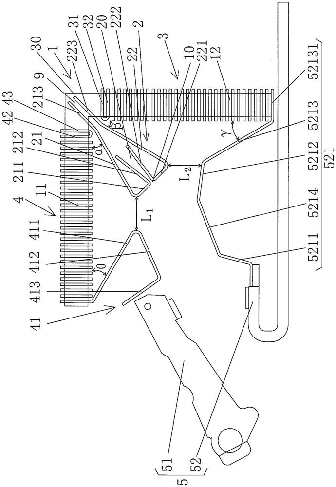
[0029] Shows a contact mechanism 5 of the structural system of the circuit breaker; shows a first arc extinguishing grid group I4 of the arc extinguishing chamber structural system, and the first arc extinguishing grid group I4 is stacked at intervals in a transverse state It is composed of several vertical arc extinguishing grids; it shows a second arc extinguishing grid group II3, which is also the structural system of the arc extinguishing chamber. Composed of transverse arc extinguishing grids, one end of the first arc extinguishing grid group I4 and the second arc extinguishing grid group II3 are adjacent to and form each other The relation of the font, the The region at the border of the glyphs constitutes an adjoining portion 30 (also referred to as “adjacent portion”, hereinafter the same).
[0030] As one of the technical effects of the technical solution provided by the present invention, an arc starting device 2 is provided at a position corresponding to the adjo...
Embodiment 2
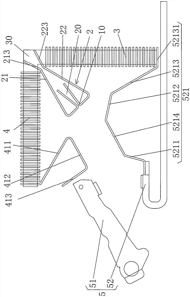
[0049] See figure 2 , the aforementioned first arc extinguishing plate end I213 is in an inclined state forming an angle with the longitudinal arc extinguishing grid, or it can be arranged on the transverse extension section 11 toward the aforementioned One end of the adjoining portion 30, the second arc-leading plate end II 223 is set in the longitudinal extension section under the state of forming an angle with the transverse arc extinguishing grid, or in the state of forming a transverse parallel with the transverse arc extinguishing grid 12 towards one end of the adjoining portion 30, and in this embodiment, the first additional grid piece I42 of the first arc-extinguishing grid group, the second additional grid piece II43 of the first arc-extinguishing grid group, and the second additional grid piece II43 of the first arc-extinguishing grid group are discarded in this embodiment. The first additional grid I31 of the second arc-extinguishing grid group and the second addi...
Embodiment 3
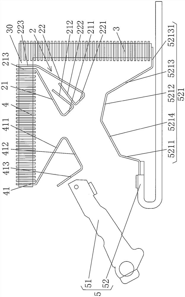
[0051] See image 3 The first arc-leading plate end I213 and the second arc-leading plate end II223 are arranged on the end of the transversely extending section 11 of the aforementioned bracket 1 facing the adjoining portion 30 in a state parallel to the longitudinal direction of the aforementioned longitudinal arc-extinguishing grid, and at the In the embodiment, the first additional grid piece I42 of the first arc-extinguishing grid group, the second additional grid piece II43 of the first arc-extinguishing grid group, and the first additional grid piece of the second arc-extinguishing grid group of the first embodiment are discarded. I31 and the second additional grid II32 of the second arc extinguishing grid group, and the rest are the same as the description of the first embodiment.
PUM
 Abstract
Description
Claims
Application Information
 - Generate Ideas
- Intellectual Property
- Life Sciences
- Materials
- Tech Scout
- Unparalleled Data Quality
- Higher Quality Content
- 60% Fewer Hallucinations
Browse by: Latest US Patents, China's latest patents, Technical Efficacy Thesaurus, Application Domain, Technology Topic, Popular Technical Reports.
© 2025 PatSnap. All rights reserved.Legal|Privacy policy|Modern Slavery Act Transparency Statement|Sitemap|About US| Contact US: help@patsnap.com