Terminal structure and micro encoder
A terminal structure and encoder technology, applied in the field of encoders, can solve problems such as inability to realize switching functions, and achieve various effects
- Summary
- Abstract
- Description
- Claims
- Application Information
AI Technical Summary
Problems solved by technology
Method used
Image

Examples
Example Embodiment
[0032] Example 1
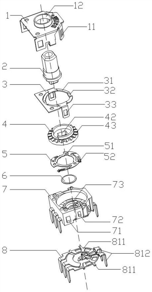
[0033] see Figures 4 to 9 , In the embodiment of the present invention, a terminal structure includes a terminal 8, which is processed by tearing and punching. The terminal 8 is provided with an angle plate 811, and the terminal 8 is also provided with a switch terminal 812. Specifically, the switch terminal 812 is arranged in the upper space of the angle plate 811, and the switch terminal 812 is independent of the coding terminal (not shown) of the terminal 8 itself. Compared with the background technology, an independent switch can be realized. Function, preferably, there is a drop between the switch terminal 812 and the angle plate 811 .
[0034] In addition, the above-mentioned terminal 8 has various forms in practical application, that is, such as Figure 4 Shown are horizontal pin form terminal 81, five-pin chip form one terminal 82, vertical pin form terminal 83, five-pin chip form two terminal 84, four-pin chip form terminal 85 and vertical chip f...
Example Embodiment
[0036] Example 2
[0037] see Figures 1 to 14 , In the embodiment of the present invention, a micro-encoder is also proposed, which includes the terminal structure described in the above-mentioned embodiment, so the micro-encoder not only has the function of the encoder, but also has the function of the switch.
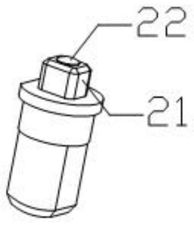
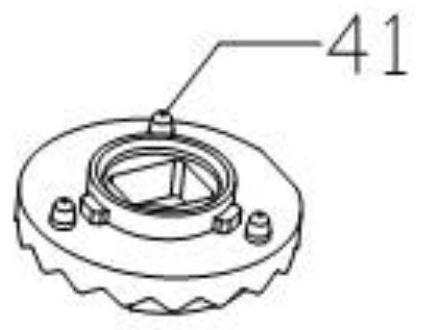
[0038] Specifically, the micro-encoder further includes a housing 1, a rotating shaft 2, a positioning piece 3, a rotor 4, a switching piece 5, a dome piece 6 and a base 7. The housing 1 and the base 7 are fastened to each other to form a space for accommodating The inner cavity of the rotating shaft 2, the positioning piece 3, the rotor 4, the switching piece 5, the dome piece 6; the rotating shaft 2, the head end protrudes from the mounting hole 12 opened on the outer casing 1, and the bottom of the rotating shaft 2 is coupled with the rotor 4, and is placed For the coupling method, a non-circular coupling method is adopted. In this embodiment, the bottom of the r...
PUM
 Abstract
Description
Claims
Application Information
 - R&D Engineer
- R&D Manager
- IP Professional
- Industry Leading Data Capabilities
- Powerful AI technology
- Patent DNA Extraction
Browse by: Latest US Patents, China's latest patents, Technical Efficacy Thesaurus, Application Domain, Technology Topic.
© 2024 PatSnap. All rights reserved.Legal|Privacy policy|Modern Slavery Act Transparency Statement|Sitemap