Robot system
A robot system and robot technology, applied in the field of robot systems, can solve the problems of robot productivity reduction, drive limitation, robot drive limitation, etc.
- Summary
- Abstract
- Description
- Claims
- Application Information
AI Technical Summary
Problems solved by technology
Method used
Image

Examples
no. 1 approach
[0026] First, the robot system according to the first embodiment will be described.
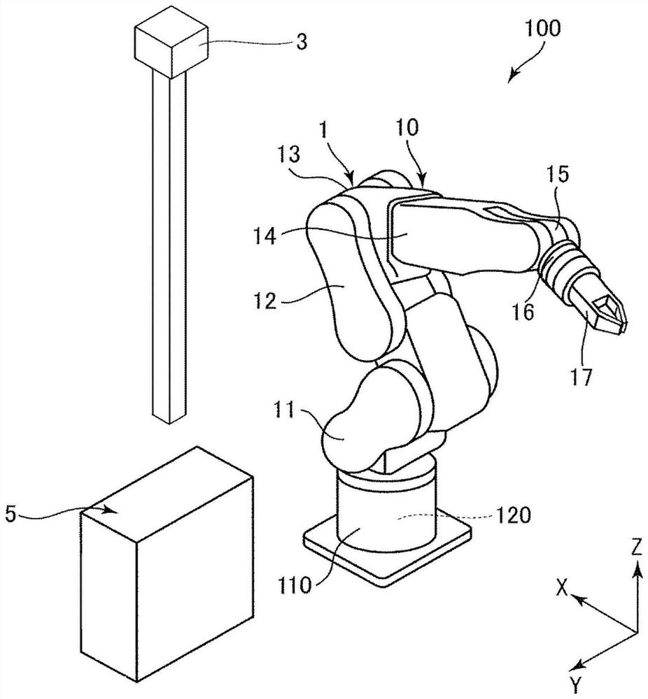
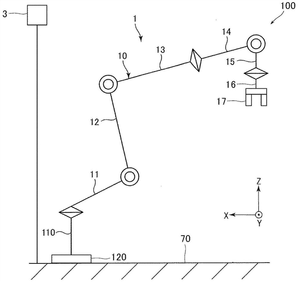
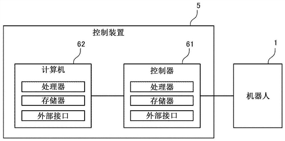
[0027] figure 1 It is a figure which shows the robot system which concerns on 1st Embodiment. figure 2 yes figure 1 A schematic diagram of the robotic system is shown. image 3 yes means figure 1 as well as figure 2 A block diagram of an example of the hardware configuration of the robot system shown. Figure 4 is used to describe in more detail image 3 functional block diagram.
[0028] In addition, in figure 1 In FIG. 3 , an X axis, a Y axis, and a Z axis are shown as three axes orthogonal to each other. In addition, in this specification, "connection" includes both the case of being directly connected and the case of being indirectly connected through an arbitrary member.
[0029] 1.1 Robot system
[0030] figure 1 The illustrated robot system 100 is used in operations such as holding, conveying, and assembling a work object. The robot system 100 includes: a robot 1 ; a cont...
no. 2 approach
[0100] Next, a robot system according to a second embodiment will be described.
[0101] Figure 8 is a schematic diagram of the robot system according to the second embodiment.
[0102] Hereinafter, the second embodiment will be described, but in the following description, the differences from the first embodiment will be mainly described, and the description of the same matters will be omitted. In addition, in Figure 8 In , the same reference numerals are assigned to the same structures as those in the first embodiment.
[0103] The second embodiment is the same as the first embodiment except that the control by the control unit 51 is different.
[0104]In the first embodiment described above, the area 1000 is set around the robot 1 , and when the person 9 enters the area 1000 , the driving of the robot 1 is restricted. In contrast, in the present embodiment, the region 1000 in which the driving of the robot 1 is restricted is divided into two stages. That is, another ...
no. 3 approach
[0118] Next, a robot system according to a third embodiment will be described.
[0119] Figure 9 to Figure 13 Each is a schematic diagram of the robot system according to the third embodiment.
[0120] Hereinafter, the third embodiment will be described, but in the following description, the differences from the first embodiment will be mainly described, and the description of the same matters will be omitted. In addition, in Figure 9 to Figure 13 In , the same reference numerals are assigned to the same structures as those in the first embodiment.
[0121] The third embodiment is the same as the first embodiment except that the control by the control unit 51 is different.
[0122] Figure 9 This is an example in which there are two persons 9A and 9B inside the imaging range 30 . on the other hand, Figure 10 This is an example in which there are three persons 9A, 9B, and 9C inside the imaging range 30 . also, Figure 9 as well as Figure 10 The shown persons 9A, 9B...
PUM
 Abstract
Description
Claims
Application Information
 - Generate Ideas
- Intellectual Property
- Life Sciences
- Materials
- Tech Scout
- Unparalleled Data Quality
- Higher Quality Content
- 60% Fewer Hallucinations
Browse by: Latest US Patents, China's latest patents, Technical Efficacy Thesaurus, Application Domain, Technology Topic, Popular Technical Reports.
© 2025 PatSnap. All rights reserved.Legal|Privacy policy|Modern Slavery Act Transparency Statement|Sitemap|About US| Contact US: help@patsnap.com