Battery physical model real-time establishing method and updating method and battery monitoring equipment
A technology of physical model and establishment method, which is applied in the direction of measuring electricity, measuring electric variables, measuring devices, etc., and can solve problems such as battery physical model update, deviation, unfavorable battery management, use, etc.
Active Publication Date: 2020-11-24
ZHUHAI MAIJU MICROELECTRONICS CO LTD
11 Cites 0 Cited by
AI-Extracted Technical Summary
Problems solved by technology
[0003] The battery physical model established by the laboratory in advance based on the chemical properties of the battery needs to be modeled and tested on the battery in advance, and it is difficult to update the battery physical model following the use of the battery
[0004...
Method used
[0140] The non-volatile memory 29 is used to store configuration values and factory calibration values to improve measurement accuracy. The external microcontroller 50 writes or reads the internal data of th...
Abstract
The invention provides a battery physical model real-time on-line establishment method. The method comprises the steps: S1, measuring an output value of a battery in at least one of a charging state,a discharging state and a non-charging and non-discharging state in real time; S2, obtaining a parameter function required for establishing a battery physical model in real time at least based on theoutput value of the battery in at least one of the charging state, the discharging state and the non-charging and non-discharging state; and S3, based on the parameter function, establishing a batteryphysical model in real time. The invention further provides a battery physical model real-time on-line updating method, a battery state and/or battery state change trend judgment method and battery monitoring equipment.
Application Domain
Electrical testing
Technology Topic
Charge and dischargeElectrical and Electronics engineering +3
Image
Examples
- Experimental program(1)
Example Embodiment
[0069] The present disclosure will be further described below with reference to the drawings and embodiments. It will be appreciated that the specific embodiments described herein are for explanation of the related content, and is not limited to the present disclosure. It will also be noted that only the portions associated with the present disclosure are shown in the drawings for ease of description.
[0070] It should be noted that the features of the present disclosure and the features in the present disclosure may be combined with each other in the case of an unable conflict. The technical solution of the present disclosure will be described in detail below with reference to the drawings.
[0071] Unless otherwise stated, the exemplary embodiments of the illustrative embodiments will be appreciated to provide exemplary features of various details of the technical idea of the present disclosure can be implemented in practice. Thus, unless otherwise stated, various embodiments / embodiments of various embodiments / embodiments may be additionally combined, separated, interchangeable, and / or re-arranged without departing from the technical idea of the present disclosure.
[0072] Using crossover lines and / or shadows in the drawings are commonly used to make the boundaries between adjacent components become clear. As such, unless otherwise stated, the existence of the cross-shadow or shadow does not convey or represent any other characteristics of the common materials, material properties, size, proportions, and components, and the components. Any preference or requirements of attribute, nature, etc. Moreover, in the drawings, the size and relative dimensions of the components can be exaggerated for clarity and / or descriptive purposes. When an exemplary embodiment can be implemented in different ways, the specific process sequence can be performed in a different order in which it is described. For example, two consecutive processes can be performed substantially simultaneously or in the order in which the described order is sequence. Further, the same reference numerals indicate the same components.
[0073] When a component is referred to as "" "on another component", "or" connected "or" bind to "another component, the component can be directly connected directly to the other component. Or directly into the other component, or there may be intermediate components. However, when the component is referred to as "directly", "" directly connected to "or" directly bonded to "another component, there is no intermediate member. To this end, the term "connection" can refer to physical connection, electrical connection, or the like, and has or does not have intermediate components.
[0074] For the purpose of describing, the present disclosure can use, such as "under ...", "in ...", "under ...", "under ... above", "upper", "in ... "," Higher "and" side (eg, "in" sidewall "in" ",", ",", ",", ",,,,,,,,,,,,,,,,,,,,,,,,,,,,,,,,,,,,,,,,,,,,,,,,,,,,,,,,,,,,,,,,,,,,,,, relation. In addition to the orientation depicted in the drawings, space relative terms are also intended to include different orientations in use, operation, and / or manufacturing. For example, if the apparatus in the drawings is flipped, it is described as "in" other components or "below" or "below", will then be positioned as "" "other components or feature" above ". Therefore, exemplary terms "below" can include two orientations "above" and "below". Further, the device can be additionally positioned (e.g., rotating 90 degrees or at other actions), and thus, the space relative descriptor used herein is explained.
[0075] The term used herein is to describe the purposes of the specific embodiments, and not to the figure, limiting. As used herein, unless the context is further clearly indicated, the singular form "one (species,", "and" said (this) "also intended to include multiple forms. Further, when the term "comprising" and / or "comprising" and their variations are used in this specification, there is a group, the components, the entire, steps, operations, components, components, and / or groups thereof, but do not exclude There is or additional one or more other features, the entire, steps, operations, components, components, and / or groups. It is also important to note that as used herein, the terms "substantially", "about" and other similar terms are used as approximate terms and are not used as a degree of terms, and they are used to explain that will be understood by those of ordinary skill in the art. The measured value, the calculated value, and / or the intrinsic deviation of the value provided.
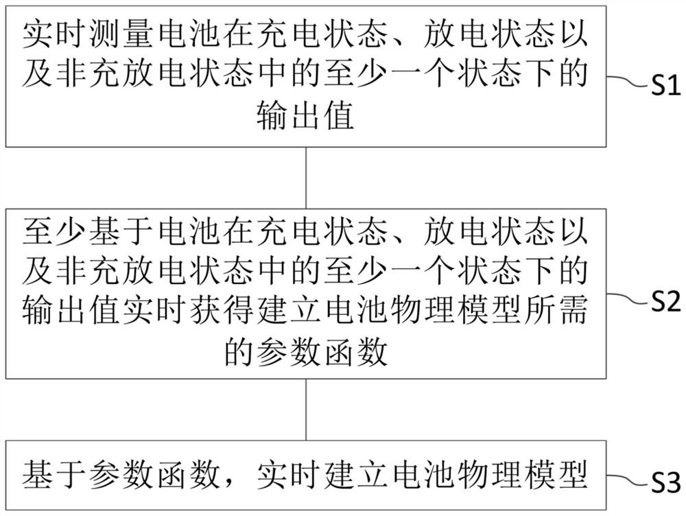
[0076] figure 1 It is a flowchart of a method according to the establishment of real time physical model of the battery according to an embodiment of the present disclosure.
[0077] like figure 1 , The real time physical model of the battery establishing method comprising: S1, real-time measurement of the battery charging state, discharging state, and at least one output value in a state where the non-discharge state; S2, at least based on the battery charging state, discharging state and at least one output value in a state of non-charge and discharge state of the battery obtained in real time to establish the desired physical parameters of the model function; and S3, based on the parameters of the function, the establishment of real-time physical model of the battery.
[0078] Wherein said output value may be an output value of the battery voltage and / or current output value. Function parameters can be obtained based on different physical model of the battery to be established differs.
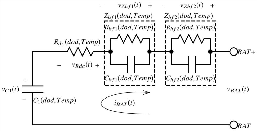
[0079] figure 2 Exemplarily shows a physical model of the battery, i.e., second order lithium physical model.
[0080] figure 2 Central C 1 (Dod, Temp) DC battery capacitance parameter, the parameter is a nonlinear function of the depth of battery discharge temperature Temp and the dod, R dc (Dod, Temp) DC battery resistance parameter, the parameter is a nonlinear function of the depth of battery discharge and temperature Temp dod, Z is hf1 (Dod, Temp) is a first order high frequency impedance parameters of the battery, the parameter is a nonlinear function of the depth of battery discharge and temperature Temp dod, Z is hf2 (Dod, Temp) is a second order high frequency impedance parameters of the battery, the parameter is a nonlinear function of the depth of battery discharge dod and the temperature Temp.
[0081] It should be noted, figure 2 Is a battery only the real time physical model of the physical model of the present disclosed method for establishing a cell line can be established in real time, real time physical model of the battery of the present disclosure can also be real-time online method for establishing other types of batteries to establish the physical model, only need to obtain a variety of battery needed to establish the physical model parameters of the function in step S2.
[0082] Wherein the method for establishing the real time physical model of the battery according to the present embodiment, the parameters of the function may include one DC capacitor function parameters, DC resistance parametric function, first order and second order function of the high frequency impedance parameters of the high frequency impedance parameters or function several.
[0083] According to the preferred embodiment of the disclosure, method of establishing the real time physical model of the battery, the battery in the discharged state, the battery output current value measured in real time by the fully charged state, that is to a discharge end of the complete discharge process (which may be constant current discharge or any load discharge), and the output voltage value of the battery temperature.
[0084] Incidentally, the measured output current value of the synchronous complete the discharge process, output voltage and battery temperature value. It will be measured multi-output current value, an output voltage value and the battery temperature.
[0085] When the output current value of the discharge complete the measurement process, the output voltage and battery temperature value, may be measured at a fixed time interval, the interval may be measured in a dynamic time.
[0086] The above-described embodiment, the DC capacitor function parameters (i.e., one parameter of the function) preferably obtained by the following method:
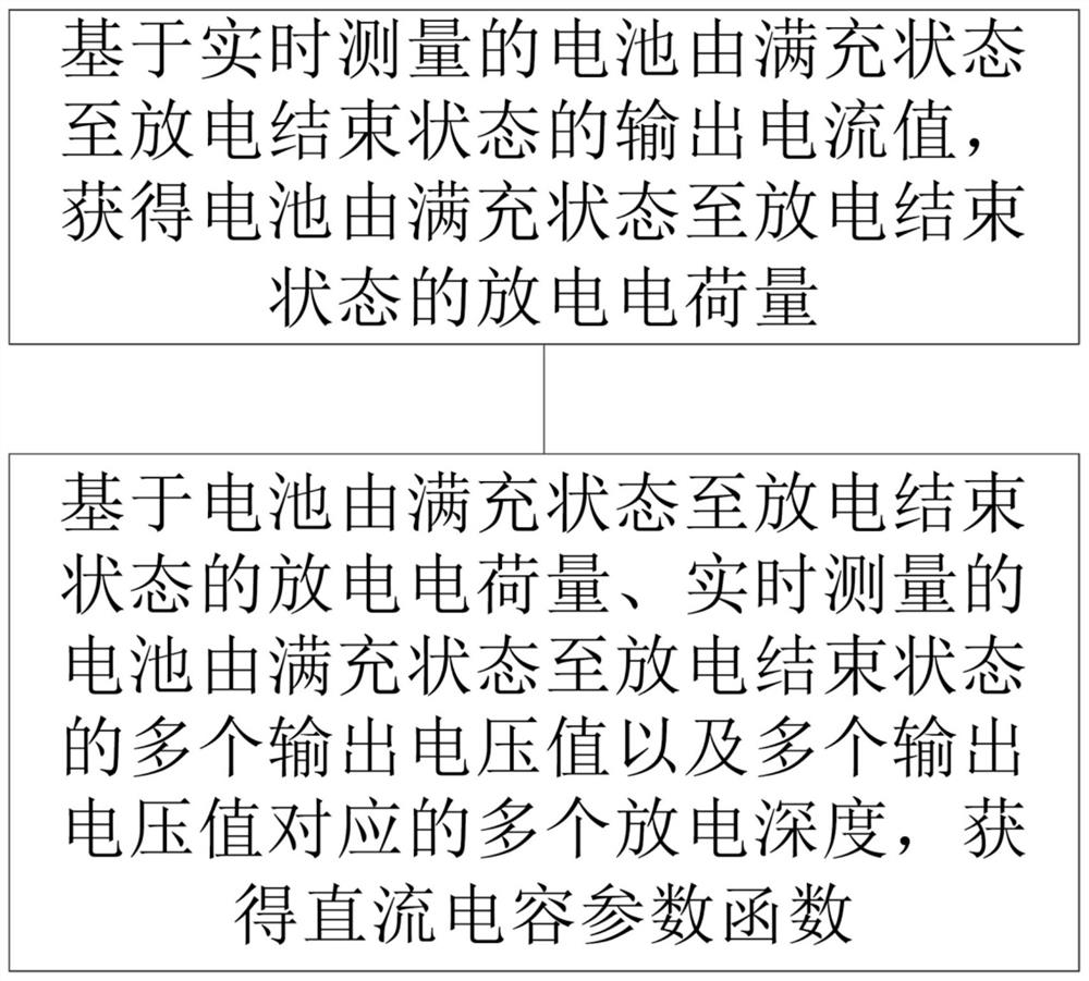
[0087] Based on real time measured by the battery fully charged to a discharge end state output current (constant current discharge may be discharged or any load), obtained by the fully charged battery to the discharge end of the discharge state of the charge amount;
[0088]Based on the amount of charge discharged by the battery fully charged to a discharge end state, measured in real time by the battery fully charged to the discharge plurality of discharge depth and a plurality of output voltage values corresponding to a plurality of voltage values output end state, the DC capacitor is obtained parameters function, function parameters DC capacitor to discharge the battery at least a function of depth.
[0089] image 3 It is a flowchart of a method of obtaining the DC capacitor function parameters.
[0090] Wherein, the battery may be discharged based on the historical record data, to obtain a plurality of discharge depth values corresponding to a plurality of output voltages of the complete discharge process.
[0091] Wherein the DC capacitor function parameters obtained by fitting algorithm data, data fitting algorithms can be used prior art data fitting algorithm.
[0092] More preferably, the DC capacitor function parameters (i.e., one parameter of the function) is obtained by the following method:
[0093] A plurality of output current value based on the complete discharge processes measured in real time (which may be any constant load discharge or discharge), the discharge charge quantity to obtain a plurality of complete discharging process (i.e., the discharge charge quantity is obtained for each complete discharge process);
[0094] Each of the plurality of full discharge based on the discharge charge quantity per complete discharging process of a plurality of full discharge process, a plurality of temperature values for each of a plurality of complete discharging process of the discharge process, a plurality of real-time measurement of the complete discharge process of the process a plurality of depth of discharge voltage values corresponding to a plurality of output for each output voltage value during discharge and a plurality of full discharge process, the parameters of the function to obtain the DC capacitor, the DC capacitor function of at least the parameter as a function of temperature, and depth of battery discharge.
[0095] Figure 4 It is a flowchart of a method of obtaining the DC capacitor function parameters.
[0096] Wherein a discharge cell based on the history record data, to obtain a plurality of discharge depth values corresponding to a plurality of output voltages of the complete discharge process.
[0097] Wherein the DC capacitor function parameters obtained by fitting algorithm data, data fitting algorithms can be used prior art data fitting algorithm.
[0098] Parametric function DC capacitor obtained as described above includes a DC coefficient of capacitance parameter with respect to the temperature change.
[0099] According to a preferred embodiment of the present disclosure embodiments, the DC resistance of the battery parameters obtained by the following method:
[0100] Charging the battery in the non-discharge state, the battery is measured and the output voltage value of the battery temperature value based on the battery discharge recording historical data, to obtain a battery depth of discharge current;
[0101] When the battery begins to discharge the charge and discharge state of a non-synchronous real time measurement of the output voltage value and the current output value, starting from the non get battery charge and discharge after the initial discharge state of the charge amount of the first predetermined time and the length of the battery charge amount reaches the initial discharge when the output voltage value;
[0102] Based on an output voltage value of the battery in a non-discharge state, the battery voltage reaches the output value of the initial discharge and the battery charge amount of a non-discharge state to the average output current reaches the initial discharge between the charge amount, the DC resistance of the battery is obtained parameter.
[0103] Figure 5 It is a flowchart of a method of obtaining the DC resistance parameters.
[0104] Wherein the non-discharge state of the battery is not charged and discharged, the battery voltage in a stable state for a long time, for example within one hour, the battery cell voltage is not more than 1mV. Measuring means for measuring a battery output voltage value at that time and the battery temperature, and battery discharge data is based on historical record, to obtain a battery depth of discharge at this time.
[0105] Each of the above embodiments, the battery discharge recording history data includes at least map data and the output voltage of the battery depth of discharge.
[0106] Wherein the first predetermined length of time is preferably a high frequency capacitance-order parameters (C hf1 (Dod, Temp)) with a first order high frequency resistance parameter (R hf1 (Dod, Temp)) the product of second order frequency capacitance parameters (C hf2 (Dod, Temp)) with a second order high frequency resistance parameter (R hf2 More than 4 times the maximum product (dod, Temp)) in, preferably 4 to 5 times.
[0107] Further, initial discharge charge amount must be less than the rated capacity of the battery with a predetermined percentage of the product, preset percentage of 1-2%.
[0108] More preferably, if Image 6 , The DC resistance function parameters (i.e., one parameter of the function) is obtained by the following method:
[0109] When the battery charge and discharge a plurality of non-state were measured value of the battery output voltage and a battery temperature value based on the battery discharge recording historical data to obtain a plurality of non-discharge depth charge and discharge state, wherein the plurality of non-discharge state of the battery in various non-discharge state of the discharge depth;
[0110] Obtaining a plurality of non-discharge state of the initial charge amount and discharge the battery when the output voltage reaches the initial discharge charge amount;
[0111] Based on an output voltage value of the battery in a plurality of non-discharge state, the battery voltage reaches the output value of the initial discharge and the battery charge amount of a non-discharge state to achieve the average output current charge amount between the initial discharge, a plurality of non- battery temperature during charge and discharge state, and when the depth of discharge of the plurality of non-discharge state of the battery to obtain DC resistance parameter of the function, the DC resistance parameter of the function to discharge the battery at least a function of depth, and temperature.
[0112] Wherein the DC resistance function parameters obtained by data fitting algorithm. Data fitting algorithms may use data fitting algorithm of the prior art.
[0113] Wherein the DC resistance of the DC resistance function parameters including parameters with respect to temperature variation factor.
[0114] The above-described embodiment, the first-order and second order high frequency impedance parameters of the high frequency impedance parameters are preferably obtained by the following method:
[0115] Charging the battery in the non-discharge state, the battery is measured and the output voltage value of the battery temperature value based on the battery discharge recording historical data, to obtain a battery depth of discharge current;
[0116] The second predetermined length of time from the start of discharge when the battery charge and discharge state of a non-real-time measurement and synchronization with the output value of the current output voltage value, an output voltage curve acquired value of the second predetermined length of time and the current output value curve ;
[0117] Voltage curve and a current output value of the output value curve for Fourier analysis to obtain a first order and second order high frequency impedance parameters of the high frequency impedance parameters.
[0118] Wherein the second predetermined length of time is preferably a high frequency capacitance-order parameters (C hf1 (Dod, Temp)) with a first order high frequency resistance parameter (R hf1 (Dod, Temp)) the product of second order frequency capacitance parameters (C hf2 (Dod, Temp)) with a second order high frequency resistance parameter (R hf2 5 times the maximum product (dod, Temp)) in less, preferably 4 to 5 times.
[0119] Figure 7 It is a flowchart of the above parameters and the first-order method for obtaining high-frequency impedance of the high frequency impedance parameters of the second order.
[0120] More preferably, if Figure 8 , The DC resistance function parameters (i.e., one parameter of the function) is obtained by the following method:
[0121] When the battery charge and discharge a plurality of non-state were measured value of the battery output voltage and a battery temperature value based on the battery discharge recording historical data to obtain a plurality of non-discharge depth charge and discharge state, wherein the plurality of non-discharge state of the battery in various non-discharge state of the discharge depth;
[0122] Voltage output curve and a current curve of the output value of the second predetermined length of time a battery is obtained by each of the plurality of non-discharge state of the non-discharge state at the start of discharge;
[0123] Each non-discharge state based on the charge and discharge state of a plurality of non-Fourier analysis of the plurality of battery temperature during charge and discharge state and non-discharge depth of the plurality of non-discharge state of the battery to obtain a high-order frequency and impedance parameters of the function of second order high frequency impedance parameters of the function, the first-order and second order function of the high frequency impedance parameters of the high frequency impedance parameters are a function of at least a function of the depth of battery discharge, and temperature.
[0124] Wherein the first order and second order function of the high frequency impedance parameters of the high frequency impedance parameters of the function data are obtained by fitting algorithm.
[0125] The method of updating the real time physical model of the battery according to an embodiment of the present disclosure, the function of the battery parameters establishing method for establishing a physical model based on a physical model of the battery of any of the above embodiments, the real time physical model of the battery for the real time updates.
[0126] The battery condition to an embodiment of the present disclosure and / or a determination method for a battery change of status, parameter changes the function of the battery physical model based on the real time updating method described above the battery physical model of the real time update process, determining battery status and / or change of status of the battery.
[0127] Wherein the battery status including battery state of charge (SOC) and / or a battery state of health (SOH).
[0128] Wherein the parametric function including a function of the DC capacitor parameters, DC resistance parametric function, first order and second order function of the high frequency impedance parameters of the high frequency impedance parameters of the function.
[0129] The method of the present physical model of the battery cell disclosed in the real time physical model can be established online real-time updated, you do not need to be modeled in advance of the test cell, and may be implemented to establish the physical optimize battery (especially lithium batteries) directly in practical applications model, so that a lithium battery model gradually approach the calculated theoretical actual value, and with the aging of the battery, the battery can be updated in real time state parameters (e.g. aging parameters), the present disclosure battery status and / or change of status of the battery Analyzing method to obtain cell status and / or change of status of the battery (e.g., the expected value of the battery aging).
[0130] Establishing a physical model of the battery of the present method for establishing the real time physical model of the battery disclosed accuracy increases with the number of discharges, the discharge current mode (constant-current discharge or the discharge of any load) and different operating temperatures, has been trained, the precise degree increased gradually.
[0131] Meanwhile, the physical model of the battery real-time online updates real-time tracking method disclosed herein can be battery in the course of the aging process, with the aging of the battery, and constantly update their physical model of the battery, as the battery has been maintained throughout the life cycle accurate estimation physical model of the battery, whereby the battery (especially lithium batteries) accurate state of charge SOC (state of charge) and a state of health SOH (state of health) of the calculated value.
[0132] The battery monitoring device according to one embodiment of the present disclosure 100, such as Figure 9As shown, the battery monitoring device 100 includes a measurement device, a measurement device real-time measuring the output value in at least one of at least one of the charging state, discharge state, and non-charged state; and the processing apparatus, the processing device is based on the battery in the charging state. , The output value in at least one of at least one in the discharge state and the non-charge state is real-time, and the parameter function required to establish the battery physical model is real-time, as well as the parameter function, and establish a battery physical model in real time.
[0133] Among them, the battery monitoring device 100 of the present embodiment preferably has Figure 9 The structure is shown.
[0134] like Figure 9 As shown, the processing device, for example, the microcontroller 50 can be implemented by performing the corresponding computer program. Figure 1 to 8 The step of the measurement step executing in the measuring device, the processing apparatus can also be a single chip, an FPGA device.
[0135] Battery monitoring device 100 includes an analog front end chip 20, microcontroller 50, and the like. The analog front end chip 20 is used to measure the output voltage of each of the batteries of the battery pack 10 consisting of a single battery 11, and measure the voltage difference between the sampling resistor 41 by the coulombi 25 through the difference lines 66a and 66b.
[0136] The temperature of the battery pack 10 is measured by a negative temperature coefficient resistor (NTC) 12 or otherwise temperature sensor disposed inside the battery pack 10.
[0137] The analog front-end chip 20 has the ability to disconnect the circuit, such as a MOSFET or any form of a circuit breaker or relay 43, 44, and the like that drives in series on the battery pack 10 output loop. The drive circuit 31 is integrated into the inside of the analog front end chip 20, and the external circuit breaker 43, 44 is controlled by the control control signal 63 and the control signal 64. The discharge MOSFET 44 prevents the battery pack 10 to externally discharge when it is used to occur. The charging MOSFET 43 prevents the external charger from charging the battery pack 10 when an abnormal occurs occurs. The fuse 42 is a redundant protection for extreme cases to prevent irreversible damage in the device and the battery.
[0138] An analog switch 21 is provided inside the analog front end chip 20, and the switching signal is controlled by the switch decoding circuit 26 for controlling the voltage of each battery of the battery pack 10 in accordance with the predetermined order. The voltage passes through the analog switch 21 as the input of the buffer 22. The battery voltage of the buffer 22 is input to the input of the analog to digital converter 23. After the conversion of the analog to digital converter 23, the digital results are stored in the random volatile memory 28. At the same time, the coulometer 25 is used to measure the voltage difference between the sampling resistor 41, and enter the measurement port of the coulombi 25 through the difference lines 66a and 66b.
[0139] The controller 27 inside the analog front-end chip 20 is, for example, a digital state machine, and is used to control the timing flow of the internal sampling conversion and other actions. Image 6 The middle mark 62 is the control line, and the mark 65 is a measuring line, and the mark 61 is a data line.
[0140] Non-volatile memory 29 is used to store configuration values and factory check values to increase measurement accuracy. The external microcontroller 50 writes or reads or reads or reads or reads or reads or reads internal data of the analog front-end chip 20 by a communication interface 24 (preferably a digital communication interface). The regulator 32 is taken from the battery pack 10.
[0141] like Figure 9 As shown, the measuring device of the battery monitoring device 100 of the present embodiment includes a negative temperature coefficient resistor 12, an analog front end chip 20, a sampling resistor 41, a fuse 42, a charging MOSFET 43, a discharge MOSFET 44, a data line 61, The control line 62, the control signal 63, the control signal 64, the measuring line 65, the difference line 66a, the difference line 66b.
[0142] It should be noted, Figure 9 The structure of the battery monitoring device 100 is only a preferred embodiment of the present disclosure, and does not constitute a particularly limited by the battery monitoring apparatus 100 of the present disclosure, the measurement device of the battery monitoring device 100, and the processing device of the battery monitoring device 100.
[0143] In the description of the present specification, a description of the reference terms "one embodiment / mode", "some embodiments", "example", "specific example" or "some examples", etc., meant to bind to this embodiment or The specific features, structures, materials, or features described in the examples are included in at least one embodiment / means or examples of the present disclosure. In the present specification, schematic representations of the above terms are not necessarily directed to the same embodiment / means or examples. Moreover, the specific features, structures, materials, or features described may be combined in any one or more embodiments / means or examples. In addition, those skilled in the art can combine and combine different embodiments or features of the present specification in the case of non-mutual contradictions.
[0144] Moreover, the term "first", "second" is used only for the purpose of describing, and cannot be understood as an indication or implies a relative importance or implicitting the number of indicated techniques. Thus, the features of "first", "second" are defined, and at least one of the features may be indicated or implicitly. In the description of the present disclosure, the meaning of "multiple" is at least two, such as two, three, etc., unless otherwise clearly specifically defined.
[0145] Those skilled in the art will appreciate that the above-described embodiments are merely illustrative of the disclosure, and is not limited to the scope of the present disclosure. For those skilled in the art, other variations or variations can also be made based on the above disclosure, and these variations or variations are still within the scope of the present disclosure.
PUM


Description & Claims & Application Information
We can also present the details of the Description, Claims and Application information to help users get a comprehensive understanding of the technical details of the patent, such as background art, summary of invention, brief description of drawings, description of embodiments, and other original content. On the other hand, users can also determine the specific scope of protection of the technology through the list of claims; as well as understand the changes in the life cycle of the technology with the presentation of the patent timeline. Login to view more.