High-temperature compressed air cooling and purifying system and using method thereof

A compressed air and purification system technology, applied in chemical instruments and methods, separation methods, damage protection, etc., can solve problems such as poor water removal and purification effects, filter blockage, safety production impact, etc., and achieve water cooling and impurity filtering effects Good, prevents filter clogging, and prevents malfunctions

Inactive Publication Date: 2020-11-27
GUANGDONG HONGDA SHAOHUA IND EXPLOSIVES CO LTD
View PDF6 Cites 2 Cited by
  • Summary
  • Abstract
  • Description
  • Claims
  • Application Information

AI Technical Summary

Problems solved by technology

[0003] However, in the extreme operating state of the original cold-drying equipment of the compressed air system (the flow rate is about 10% greater than that of the compressor), it can only be reduced from 60-85°C to about 40-50°C. When the weather is hot, the energy efficiency is even higher. Low
Moreover, the water removal and purification effect is poor. Due to the humid weather in the south, a large amount of moisture in the compressed air is transported to the final filter with various impurities, which leads to premature blockage of the filter and the entry of moisture, which makes various pneumatic components rust and damage, and eventually Various failures of machinery and equipment occur irregularly, which has a great impact on safe production and cannot meet the requirements of high-quality compressed air required by the production workshop.

Method used


Image

  • High-temperature compressed air cooling and purifying system and using method thereof
  • High-temperature compressed air cooling and purifying system and using method thereof

Examples

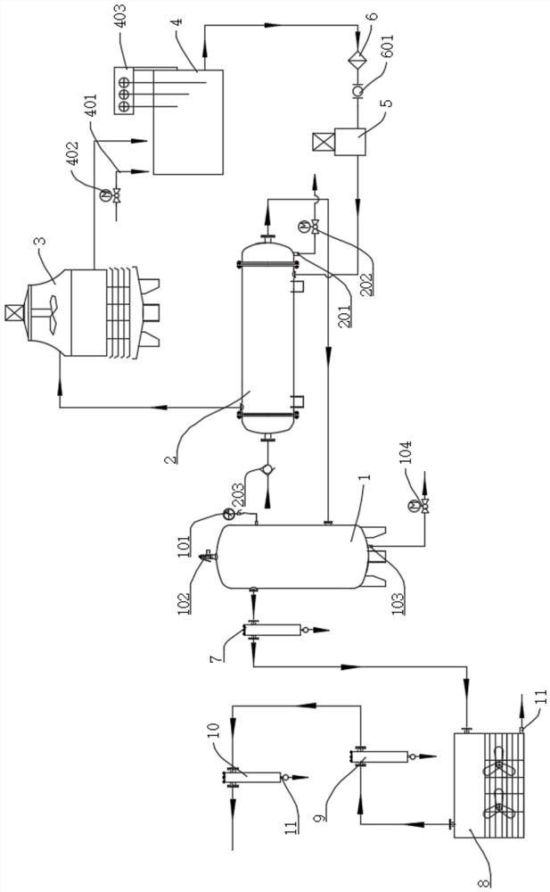
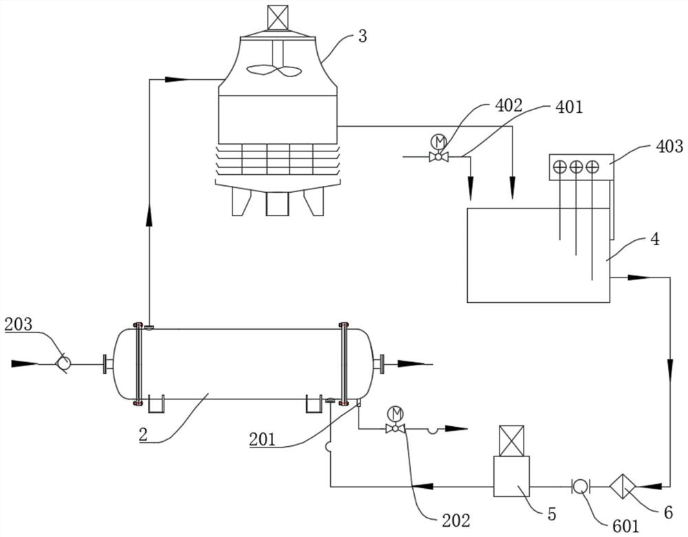

Embodiment Construction

[0022] The present invention will be described in detail below in conjunction with the accompanying drawings and embodiments.

[0023] It is worth noting that the orientation words such as "up" and "down" involved in this article are all determined relative to the perspective of the drawings, and are only for the convenience of description, and cannot be understood as limitations on the technical solution.

[0024] refer to figure 1 , figure 2 , a high-temperature compressed air cooling and purification system, including a primary cooling device, an air storage tank 1 and a secondary cooling and filtering device, the air outlet of the primary cooling device is connected to the air storage tank 1, and the air outlet of the air storage tank 1 is connected to the secondary Cool filter unit.

[0025] Among them, the primary cooling device includes a heat exchanger 2, a cooling tower 3, a water storage tank 4 and a pipeline pump 5, the heat exchanger 2 is a straight tube heat ex...


PUM


Abstract

The invention relates to a high-temperature compressed air cooling and purifying system and a using method thereof. The high-temperature compressed air cooling and purifying system comprises a first-stage cooling device, an air storage tank and a second-stage cooling and filtering device, wherein an air outlet of the first-stage cooling device is connected with the air storage tank, and an air outlet of the air storage tank is connected with the second-stage cooling and filtering device; the first-stage cooling device comprises a heat exchanger, a water cooling tower, a water storage tank anda pipeline pump; high-temperature compressed gas is introduced into a gas inlet of the heat exchanger; a water outlet of the heat exchanger is connected with a water inlet of the water cooling tower;a water outlet of the water cooling tower is connected with a water inlet of the water storage tank; a water outlet of the water storage tank is connected with a water pumping port of the pipeline pump; a water outlet of the pipeline pump is connected with the heat exchanger; the water storage tank is also connected with an external water supply pipe; and the water storage tank is provided with water level electrodes. According to the system, compressed air can be greatly cooled, and moisture in the compressed air can be automatically discharged; the water removal and purification effects aregood, filter blockage and pneumatic element corrosion damage can be prevented, equipment faults are prevented, production safety is guaranteed, and the requirement of a production workshop for compressed air is met.

Description

technical field [0001] The invention relates to the technical field of air cooling and purification, more specifically, it relates to a high-temperature compressed air cooling and purification system and its application method. Background technique [0002] Compressed air is the second largest power source next to electricity, and it is also a process gas source with multiple uses. Its application range covers petroleum, chemical industry, metallurgy, electric power, machinery, light industry, textile, automobile manufacturing, electronics, air Compressor food, medicine, biochemical, national defense, scientific research and other industries and departments. In summer, the inlet temperature of the compressor is high, and the outlet temperature of the compressed air is also high, so a cooling device is also required in the compressed air system to process the compressed air into a dry gas with a certain temperature and relative humidity before use. [0003] However, in the e...

Claims


Application Information

Patent Timeline
IPC IPC(8): B01D46/00B01D46/42F28D21/00F28F19/01
CPCB01D46/0012B01D46/4263F28D21/00F28F19/01B01D46/62
Inventor 刘韶文邱平夫
Owner GUANGDONG HONGDA SHAOHUA IND EXPLOSIVES CO LTD
Why Eureka
Try Eureka