
Control valve comprising a sealing contour on a sleeve-shaped hydraulic guide element, and component comprising a control valve and camshaft phaser

A technology of guiding components and control valves, which is applied to engine components, valve devices, machines/engines, etc., and can solve problems such as difficult adjustment of control pistons, control valve leaks, and blockages

Active Publication Date: 2020-11-27
SCHAEFFLER TECH AG & CO KG
View PDF25 Cites 0 Cited by
  • Summary
  • Abstract
  • Description
  • Claims
  • Application Information

AI Technical Summary

Problems solved by technology

[0003] The disadvantage of general embodiments with hydraulic guiding elements made of plastic has been found to be disadvantageous, since in some cases, due to production-related tolerances within tolerance limits, control valves develop leaks during operation and thus Relatively high leakage, or relatively difficult adjustment of the control piston, including clogging

Method used


Image

  • Control valve comprising a sealing contour on a sleeve-shaped hydraulic guide element, and component comprising a control valve and camshaft phaser
  • Control valve comprising a sealing contour on a sleeve-shaped hydraulic guide element, and component comprising a control valve and camshaft phaser
  • Control valve comprising a sealing contour on a sleeve-shaped hydraulic guide element, and component comprising a control valve and camshaft phaser

Examples


Embodiment Construction

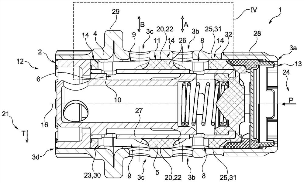
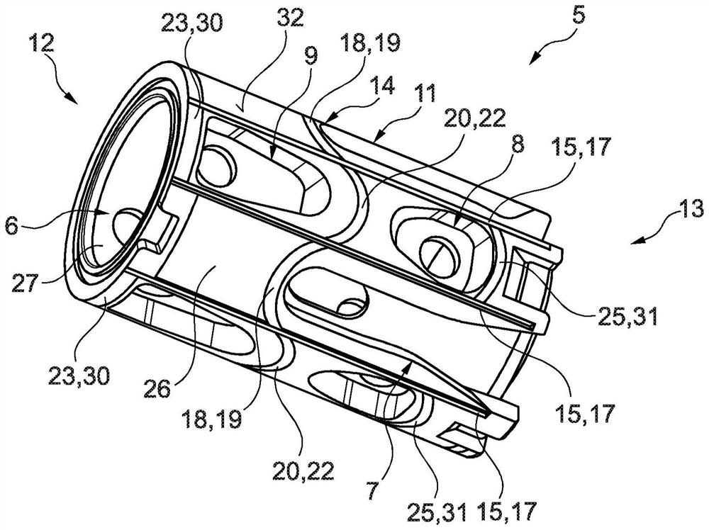
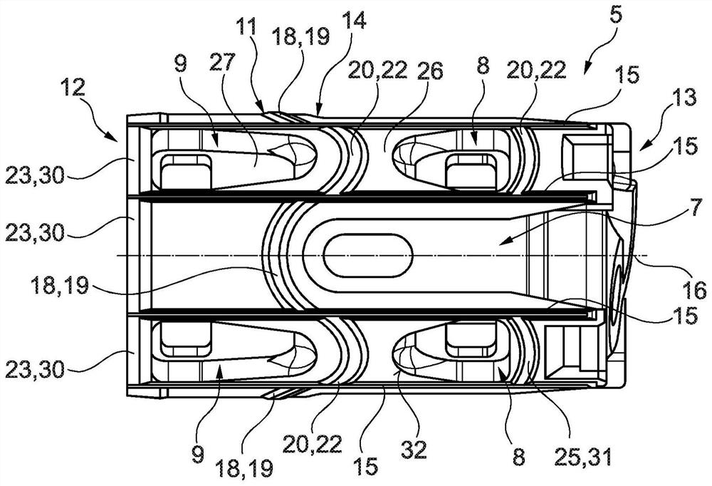
[0032] figure 1 The control valve 1 according to the invention is shown in its basic construction. The control valve 1 is generally designed as a central valve and, when used to control a hydrodynamic camshaft phaser, is correspondingly inserted radially into the rotor of the camshaft phaser. The control valve 1 thus forms a plurality of connections 3a, 3b, 3c, 3d which, during operation, are hydraulically connected to the inlet 24 (P corresponds to the pump side), the outlet 21 ( T corresponds to the tank side) and working chambers A, B. Different states of the camshaft phaser are generally achieved during operation depending on the position of the control piston 10 of the control valve 1 .

[0033] The control valve 1 has a hollow formed screw body 4 with connection portions 3a to 3d which, during operation, are screwed onto corresponding receptacles on the camshaft, thereby attaching the rotor of the camshaft phaser to the camshaft . Thus, among other things, the radial...


PUM


Abstract

The invention relates to a control valve (1) for a hydraulic camshaft phaser, comprising: a screw body (4) having a cavity (2) and a plurality of connections (3a, 3b, 3c, 3d) opening into said cavity(2); a sleeve-shaped hydraulic guide element (5) which is firmly inserted radially inside the cavity (2) and at least part of which consists of plastic, wherein the hydraulic guide element (5) has a plurality of pressure-medium channels (7, 8, 9) which open into its radial interior (6) and each of which is connected to at least one of the connections (3a, 3b, 3c, 3d); and comprising a control piston (10) displaceably accommodated in the hydraulic guide element (5), wherein a sealing contour (14), which bears against the screw body (4) and seals off the pressure-medium channels (7, 8, 9) from one another and / or from axial ends (12, 13) of the hydraulic guide element (5), is provided on a radial outer side (11) of the hydraulic guide element (5).

Description

technical field [0001] The invention relates to a control valve for a hydrodynamic camshaft phaser of an internal combustion engine, in particular used in the field of automotive engineering, the control valve having a screw body with a cavity and a valve opening to this cavity Connections; a sleeve-shaped hydraulic guiding element, at least partially made of plastic, firmly inserted radially inside said cavity (relative to the central longitudinal axis of said control valve ), wherein the hydraulic guiding element has a plurality of pressure medium channels, the plurality of pressure medium channels open to the radially inward of the hydraulic guiding element, the plurality of pressure medium channels are each connected to one of the connecting parts and A control piston is displaceably accommodated in the hydraulic guiding element, ie in the interior of the hydraulic guiding element, wherein the connections are interconnected according to the position of the control piston. ...

Claims


Application Information

Patent Timeline
IPC IPC(8): F01L1/344
CPCF01L1/3442F01L2001/34426F01L2001/34433F01L2001/34479
Inventor 大卫·克勒克里斯蒂安·贝尔夫特延斯·霍佩
Owner SCHAEFFLER TECH AG & CO KG
Learn More