Check patentability & draft patents in minutes with Patsnap Eureka AI!

Unit cell and manufacturing method therefor

A cell and cell manufacturing technology, applied in the field of manufacturing the cell cell, can solve problems such as resistance increase, and achieve the effects of easy stacking, stacking, and performance improvement

Pending Publication Date: 2020-12-01
LG ENERGY SOLUTION LTD
View PDF5 Cites 2 Cited by
  • Summary
  • Abstract
  • Description
  • Claims
  • Application Information

AI Technical Summary

Problems solved by technology

[0012] Therefore, the main object of the present invention is to provide a unit cell with a new structure and a method of manufacturing the same, in which the distance between the positive current collector and the negative current collector is minimized to solve the problem when ions and electrons move. The problem of increased resistance, thus improving battery performance

Method used


Image

  • Unit cell and manufacturing method therefor
  • Unit cell and manufacturing method therefor
  • Unit cell and manufacturing method therefor

Examples


no. 1 approach

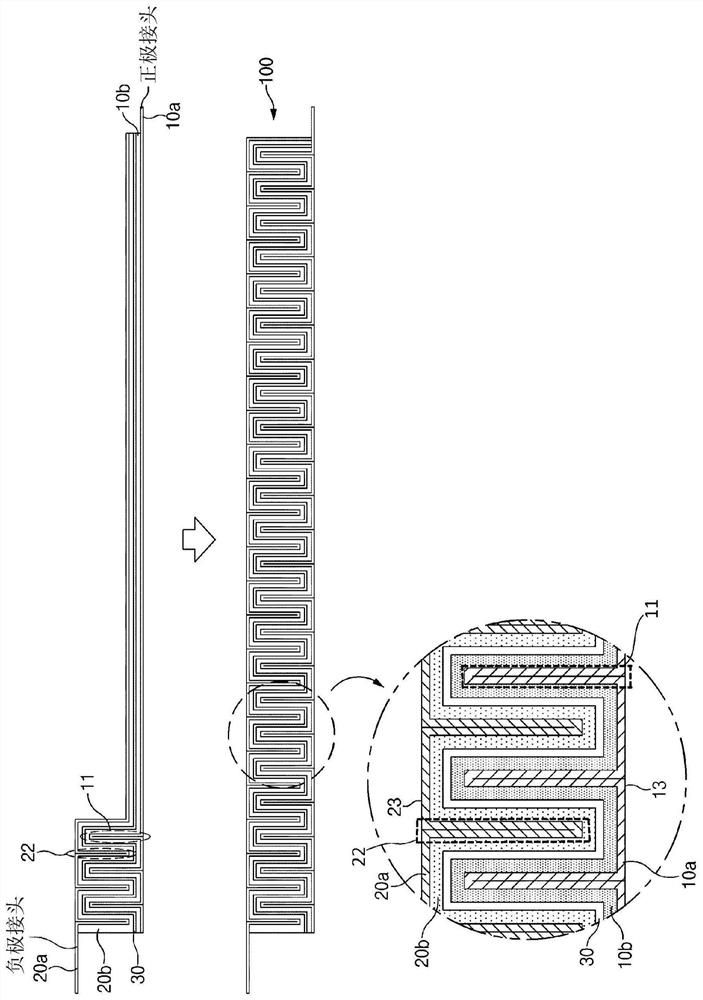
[0038] A method for manufacturing the unit cell 100 in which the distance between the positive electrode current collector 10 a and the negative electrode current collector 20 a is minimized will be described according to the first embodiment.

[0039] figure 2 are side views showing states before and after stacking the positive electrode 10 , the separator 30 , and the negative electrode 20 according to the present invention. image 3 is a side view showing a state where a positive electrode, a separator, and a negative electrode are stacked and then folded in a zigzag shape to form wrinkles thereafter.

[0040] refer to figure 2 and image 3 , in the manufacturing method according to the present embodiment, a single-sided positive electrode and a single-sided negative electrode are provided. That is, the manufacturing method according to this embodiment of the present invention includes the step of applying the positive electrode active material 10b to one surface of th...

no. 2 approach

[0052] According to the second embodiment, the unit cell 100 in which the distance between the positive electrode current collector 10 a and the negative electrode current collector 20 a is minimized will be described.

[0053] The unit cell 100 according to the present invention has a feature that the negative electrode 20 , the separator 30 and the positive electrode 10 are stacked one by one and then continuously folded in a zigzag shape to form a plurality of folds.

[0054] In the positive electrode, the positive electrode active material 10b is applied to only one surface of the positive electrode current collector 10a, and in the negative electrode 20, the negative electrode active material 20b is applied to only one surface of the negative electrode current collector 20a. The cathode 10 and the anode 20 are stacked such that the cathode active material 10b and the anode active material 20b face each other with the separator 30 therebetween. Here, each of the positive e...


PUM


Abstract

A unit cell of the present invention comprises: a separator; a cathode in which a cathode active material is applied to the surface of a cathode current collector and the cathode active material is stacked so as to make contact with one surface of the separator; and an anode in which an anode active material is applied to the surface of an anode current collector and the anode active material is stacked so as to make contact with the other surface of the separator, wherein the anode, the separator, and the cathode, in a stacked state, are folded in a zigzag manner so as to form a plurality ofwrinkles. A method for manufacturing a unit cell, according to the present invention, comprises the steps of: applying a cathode active material to the surface of a cathode current collector; applyingan anode active material to the surface of an anode current collector; stacking an anode, a separator, and a cathode so that the cathode active material makes contact with one surface of the separator and the anode active material makes contact with the other surface of the separator; and folding the anode, the separator, and the cathode, in a stacked state, so as to form wrinkles.

Description

technical field [0001] This application claims priority from Korean Patent Application No. 10-2019-0021382 filed on February 22, 2019, the entire contents of which are hereby incorporated by reference. [0002] The present invention relates to a unit cell in which a negative electrode, a separator, and a positive electrode are sequentially stacked, and more particularly, to a unit cell having a structure that is advantageous due to smoother movement of ions and electrons when compared with the structure of a cell unit according to the prior art. A unit cell with a performance-enhancing structure, and a method for manufacturing the unit cell. Background technique [0003] Batteries that store electrical energy can generally be classified into primary batteries and secondary batteries. A primary battery is a one-time consumption battery. On the other hand, a secondary battery is a rechargeable battery manufactured by using a material capable of repeating an electric current ...

Claims


Application Information

Patent Timeline
Patent Type & Authority Applications(China)
IPC IPC(8): H01M10/0583H01M2/26H01M10/052H01M10/04H01M4/139H01M50/531
CPCH01M10/052H01M10/0583Y02E60/10H01M50/531Y02P70/50H01M10/0431H01M50/46H01M4/139H01M50/538H01M50/466H01M4/70H01M4/64
Inventor 权俊
Owner LG ENERGY SOLUTION LTD
Features
  • R&D
  • Intellectual Property
  • Life Sciences
  • Materials
  • Tech Scout
  • Unparalleled Data Quality
  • Higher Quality Content
  • 60% Fewer Hallucinations
Learn More