FPGA-based circuit module test method

A technology of circuit modules and testing methods, applied in digital circuit testing, electronic circuit testing, etc., can solve problems such as the inability to simulate the use environment of circuit modules such as IP cores, and achieve accurate test results

Active Publication Date: 2020-12-04
BEIJING MXTRONICS CORP +1
View PDF9 Cites 1 Cited by
  • Summary
  • Abstract
  • Description
  • Claims
  • Application Information

AI Technical Summary

Problems solved by technology

Although this test method is simple and easy, it cannot simulate the real use environment of circuit modules such as IP cores in FPGAs.

Method used


Image

  • FPGA-based circuit module test method
  • FPGA-based circuit module test method
  • FPGA-based circuit module test method

Examples


Embodiment 1

[0040] Such as figure 1 As shown, a kind of FPGA-based circuit module testing method provided by Embodiment 1 of the present invention comprises the following steps:

[0041] S101: Obtain a circuit netlist of a target circuit module, wherein at least one first test port of the target circuit module is led out to at least one first hard macrocell.

[0042] Here, the target circuit module is the circuit module to be tested in this embodiment, for example, an IP core that needs to be provided to the user.

[0043] S102: Obtain a circuit netlist of the test circuit module, wherein at least one second test port of the test circuit module is led out to at least one second hard macrocell.

[0044] Here, the test circuit module may include the call logic of the target circuit module, and may also include the test logic of the target circuit module.

[0045] In order to make the target circuit module and the test circuit module independent of each other, the circuit design of the tar...

Embodiment 2

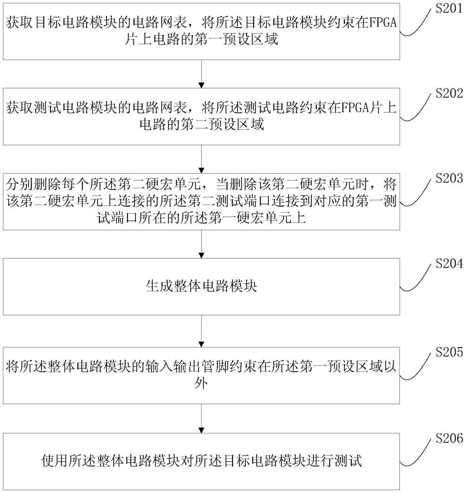
[0053] Such as figure 2 As shown, Embodiment 2 also provides another circuit module testing method, including the following steps:

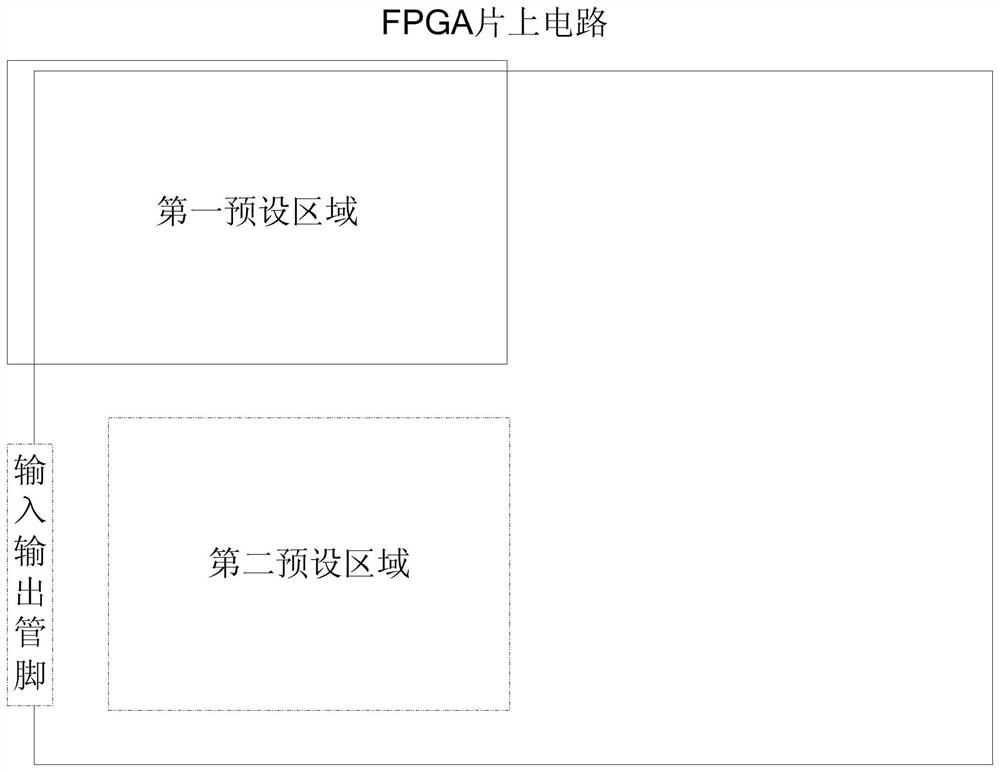
[0054] S201: Obtain a circuit netlist of a target circuit module, and constrain the target circuit module to a first preset area of ​​an FPGA on-chip circuit.

[0055] In order to further separate the target circuit module from the test circuit module, the target circuit module can be constrained in the first preset area of ​​the FPGA on-chip circuit, for example, as image 3 As shown, the target circuit module is constrained to the upper left corner of the FPGA on-chip circuit. image 3 It is only a constraint method of the target circuit module, and it does not limit that the target circuit module must be constrained in the upper left corner. The target circuit module can be constrained in any position of the circuit on the FPGA chip. Since the target circuit module is usually a circuit that completes a specific function, and it is best to b...


PUM


Abstract

The invention discloses an FPGA-based circuit module test method. The method comprises the steps of 1) obtaining a circuit netlist of a target circuit module; 2) obtaining a circuit netlist of a tested circuit module; 3) generating a circuit netlist of a whole circuit module according to the circuit netlist of the target circuit module and the circuit netlist of the tested circuit module, specifically, correspondingly connecting a test port of the tested circuit module to a hard macro cell of the target circuit module, and deleting the hard macro cell corresponding to the tested circuit module; or correspondingly connecting the test port of the target circuit module to the hard macro cell of the tested circuit module, and deleting the hard macro cell corresponding to the target circuit module; and 4) testing the target circuit module by using the circuit netlist of the whole circuit module obtained in the step 3). According to the invention, the real use environment that the IP core and other circuit modules in the FPGA are usually used as one part of the whole circuit is simulated, so that the test result is more accurate.

Description

technical field [0001] The invention relates to a circuit testing method, in particular to an FPGA-based curing unit testing method. Background technique [0002] Field Programmable Gate Array (Field Programmable Gate Array, FPGA) is a commonly used programmable logic circuit, which can provide users with flexible and rich logic resources and realize various user designs. [0003] In the commercial field, some mature designs are usually packaged into circuit modules such as IP (Intellectual Property) cores, and provided directly to users to save users' development costs. These IP cores are usually provided to users in the form of open source source code, circuit netlist or solidified circuit. [0004] Regardless of the way it is provided to users, it is necessary to conduct exhaustive and comprehensive tests on the IP core before providing it to ensure that the function of the provided IP core is correct. Commonly used test methods in the prior art generally regard the des...

Claims


Application Information

Patent Timeline
IPC IPC(8): G01R31/317G01R31/319
CPCG01R31/317G01R31/319Y02D10/00
Inventor 周婧王硕陈雷庞永江马筱婧席培培董晗张璐杜忠
Owner BEIJING MXTRONICS CORP
Why Eureka
Try Eureka