Check patentability & draft patents in minutes with Patsnap Eureka AI!

Airport unmanned aerial vehicle control area division method based on risk assessment

A UAV and risk technology, applied in aircraft traffic control, traffic control system, aircraft navigation/guidance tools, etc., can solve the lack of ground risks, the complexity of the airport control area designation system, and the insufficient accuracy of the arrival and departure track designation and other issues to achieve an accurate estimate

Active Publication Date: 2020-12-08
THE SECOND RES INST OF CIVIL AVIATION ADMINISTRATION OF CHINA
View PDF7 Cites 4 Cited by
  • Summary
  • Abstract
  • Description
  • Claims
  • Application Information

AI Technical Summary

Problems solved by technology

[0005] For example, the applicant’s previous research proposed that the patent application number is 201911306980.7, and the title of the invention is "A Method for Delineating the Control Area of ​​Airport UAVs Based on Collision Risk". Considering the complexity of the designation system for the control area of ​​different airports, the accuracy of the designation of the arrival and departure track is not enough, and it does not meet the more accurate and simplified management requirements of the existing airports.

Method used


Image

  • Airport unmanned aerial vehicle control area division method based on risk assessment
  • Airport unmanned aerial vehicle control area division method based on risk assessment
  • Airport unmanned aerial vehicle control area division method based on risk assessment

Examples


Embodiment Construction

[0066] In order to make the object, technical solution and advantages of the present invention clearer, the present invention will be further described in detail below in conjunction with the accompanying drawings and embodiments. It should be understood that the specific embodiments described here are only used to explain the present invention, not to limit the present invention.

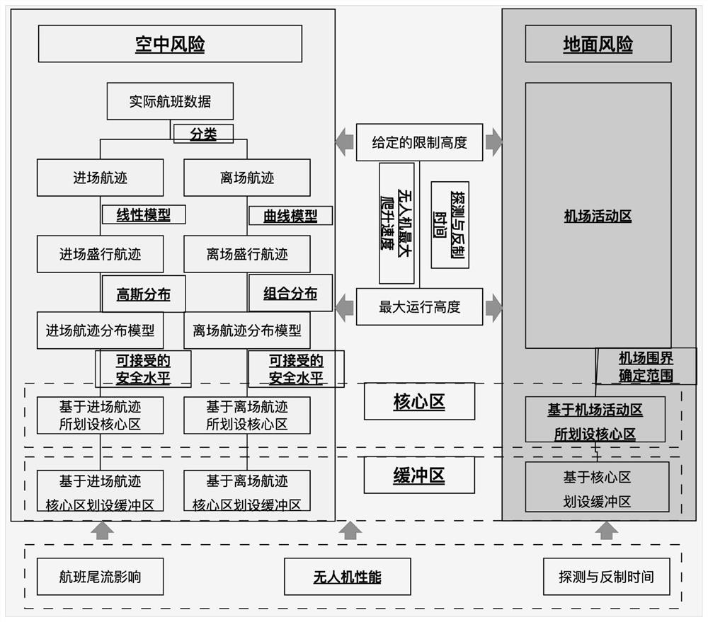
[0067] The present invention proposes a method for setting up a UAV control area around an airport, which takes into account two main risks, air risk and ground risk. The air risk mainly refers to the air collision risk between the UAV and the flight, and the ground risk mainly refers to the risk of the UAV hitting the airport personnel, taxiing aircraft or other facilities. The flow chart of the method for delineating drone control areas in this application, such as figure 1 shown.

[0068] S1 Based on the flight performance of drones, the detection and countermeasure time of drones, the obstacl...


PUM


Abstract

The invention provides an airport unmanned aerial vehicle management and control area division method based on risk assessment, which comprises the following steps: establishing an unmanned aerial vehicle management and control area model according to air risks and ground risks, wherein an unmanned aerial vehicle management and control area is a union set of an air risk core area, an air risk buffer area, a ground risk core area and a ground risk buffer area; marking a boundary in the vertical direction of an unmanned aerial vehicle control area around the airport; dividing an air risk core area; dividing a ground risk core area; calculating a buffer area horizontal extension distance based on the divided ground risk core area horizontal boundary and the divided air risk core area horizontal boundary, and respectively obtaining a ground risk buffer area horizontal boundary and an air risk buffer area horizontal boundary, and obtaining a ground risk buffer area and an air risk buffer area by combining the vertical boundary of the unmanned aerial vehicle control area. According to the division method, the air risk and the ground risk are comprehensively considered, the unmanned aerial vehicle management and control area division model is established by taking the unmanned aerial vehicle as an object, and two sets of track transverse distribution models are established in combination with the characteristics of each runway entering and leaving program, so that accurate division of the unmanned aerial vehicle management and control area is realized; the method is of great significance to various principles of airport balance safety, high efficiency and economy.

Description

technical field [0001] The invention relates to the technical field of air traffic control, in particular to the air operation management of unmanned aerial vehicles. Background technique [0002] In recent years, the application of unmanned aerial vehicles (UA) in the public and commercial fields has grown rapidly, especially in very low altitude (VLL) airspace below 500 feet. Some typical examples include aerial photography, package delivery, surveillance, agriculture, disaster management, etc., bringing new modes to urban air mobility (UAM) and broadening the utilization of conventional airspace. However, with the increase of drone activities near the airport, the safety management of the airport will also face more severe challenges. [0003] To prevent the multiple risks posed by drones operating around airports, especially collisions between drones and flights, geofencing is beginning to be widely used to define protective boundaries around geographic points that unma...

Claims


Application Information

Patent Timeline
IPC IPC(8): G08G5/00
CPCG08G5/006G08G5/0069
Inventor 张建平邹翔谢方泉吴卿刚
Owner THE SECOND RES INST OF CIVIL AVIATION ADMINISTRATION OF CHINA
Features
  • R&D
  • Intellectual Property
  • Life Sciences
  • Materials
  • Tech Scout
  • Unparalleled Data Quality
  • Higher Quality Content
  • 60% Fewer Hallucinations
Learn More