Charging control system and control method

A charging control method and charging control technology, applied in the field of automobiles, can solve problems such as reducing system reliability, increasing single vehicle cost, and vehicle failure to start, so as to reduce system complexity, improve system reliability, and avoid failure to start.

Pending Publication Date: 2020-12-15
EVERGRANDE NEW ENERGY AUTOMOTIVE INVESTMENT HLDG GRP CO LTD
View PDF0 Cites 3 Cited by
  • Summary
  • Abstract
  • Description
  • Claims
  • Application Information

AI Technical Summary

Problems solved by technology

[0003] The existing electric vehicle pre-charging circuit requires at least one pre-charging resistor and one pre-charging relay, which not only increases the cost of the single vehicle, but also increases the difficulty of the space layout of the battery pack, and if the pre-chargi

Method used


Image

  • Charging control system and control method
  • Charging control system and control method
  • Charging control system and control method

Examples


Example Embodiment

[0043] DETAILED DESCRIPTION OF THE DRAWINGS will be further described below.

[0044] It is readily understood that, in accordance with the technical solution of the present invention, various structural methods and implementations of the general technicians can be replaced with each other in the spirit of the present invention. Therefore, the following detailed description and the accompanying drawings are merely illustrative of the technical solutions of the present invention, and it is not considered to be limited or limited to the present invention.

[0045] In this specification, or may be mentioned, lower, left, right, front, rear, front, back, top, bottom, is defined relative to the configuration shown in each of the drawings, they are The relative concept is therefore possible to perform correspondingly variation depending on the different positions thereof. Therefore, these or other orientations should not be interpreted as limiting terms.

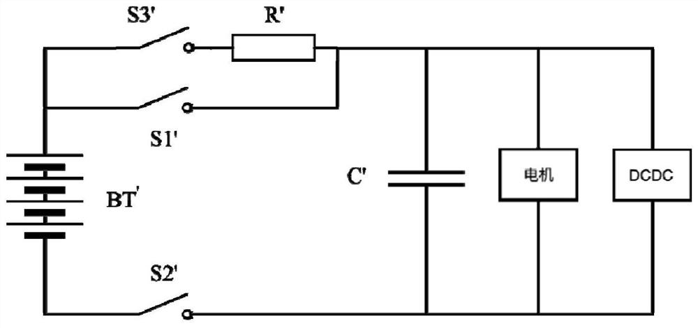
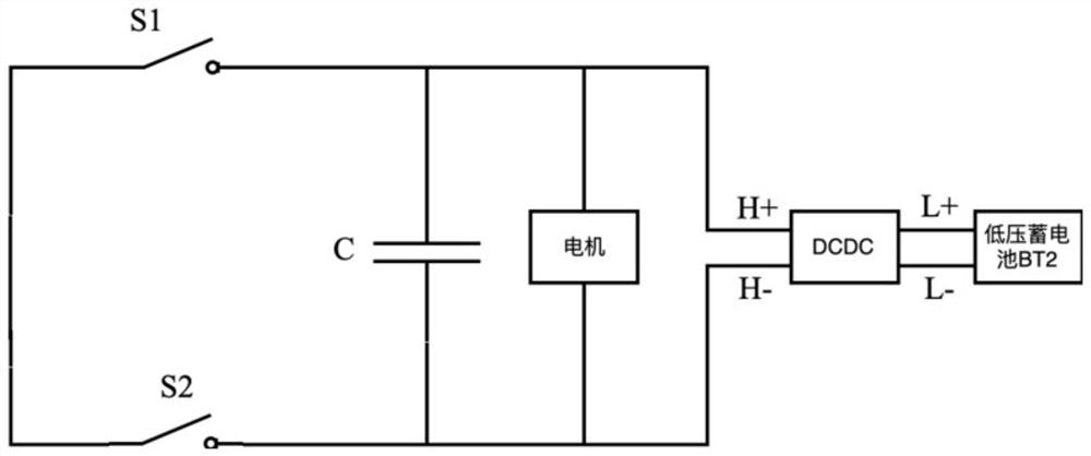
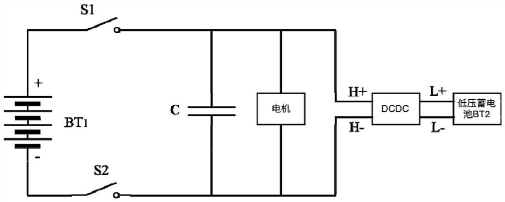
[0046] like figure 2 , The prese...


PUM


Abstract

The invention provides a charging control system and a charging control method. The system comprises a controller, a low-voltage storage battery, a DC-DC converter, a positive relay, a negative relayand a capacitor. According to the invention, the low-voltage storage battery, the DC-DC converter, the positive relay and the negative relay are sequentially connected in series to form a pre-chargingloop, and when a vehicle starting signal is received for high-voltage power-on operation, the controller controls the working states of the positive relay, the negative relay and the DC-DC converter,so as to enable the low-voltage storage battery to pre-charge the capacitor without a pre-charging relay and a pre-charging resistor, thereby reducing the cost and the system complexity, and improving the system reliability.

Description

technical field [0001] The invention relates to the technical field of automobiles, in particular to a charging control system and a control method. Background technique [0002] Electric vehicles need to be powered on at high voltage before starting. In order to prevent the high voltage of the power battery from being directly loaded on the bus terminal of the external high-voltage electrical appliance, causing damage to the bus capacitor and electrical appliances, it is necessary to slowly load the voltage to the bus terminal of the electrical appliance. At present, electric vehicles are realized by designing special pre-charging circuits, such as figure 1 As shown, the existing electric vehicle pre-charging circuit includes a power battery BT', a positive relay S1' set at the positive end of the outer high-voltage bus, a negative relay S2' set at the negative end of the outer high-voltage bus, and a pre-charging relay S3' , pre-charging resistance R', capacitor C', and h...

Claims


Application Information

Patent Timeline
IPC IPC(8): H02J7/00B60L53/00
CPCB60L53/00H02J7/0068H02J7/007H02J7/345H02J2207/50Y02T10/70Y02T10/7072Y02T10/72Y02T10/92Y02T90/14
Inventor 吴康
Owner EVERGRANDE NEW ENERGY AUTOMOTIVE INVESTMENT HLDG GRP CO LTD
Why Eureka
Try Eureka