Turbine engine and method of collecting gas stream in turbine engine

A technology of turbines and airflow, applied in the direction of machines/engines, gas turbine devices, components of pumping devices for elastic fluids, etc., to achieve the effect of reducing mass and reducing head loss

Active Publication Date: 2020-12-15
SAFRAN AIRCRAFT EGINES
View PDF6 Cites 0 Cited by
  • Summary
  • Abstract
  • Description
  • Claims
  • Application Information

AI Technical Summary

Problems solved by technology

The patent does not address structures that include a downstream compressor disk that includes a central hole that allows airflow to flow

Method used


Image

  • Turbine engine and method of collecting gas stream in turbine engine
  • Turbine engine and method of collecting gas stream in turbine engine
  • Turbine engine and method of collecting gas stream in turbine engine

Examples


Example Embodiment

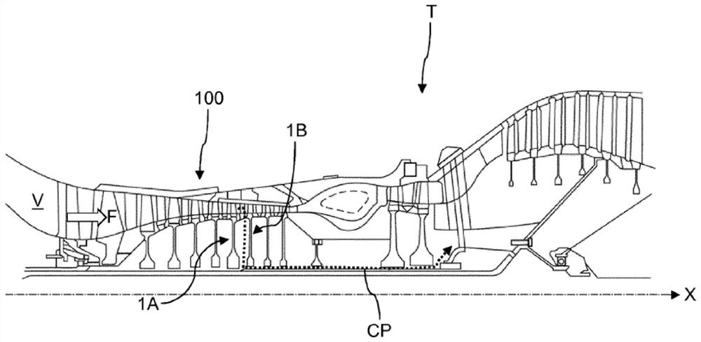
[0038] refer to Figure 4 , Figure 4 A turbine with a gas flow collection loop is shown in accordance with an embodiment of the present invention.

[0039] As previously mentioned, the turbine extends longitudinally along the X-axis and includes a main duct V in which the gas flow F flows from upstream to downstream. In the following, the terms "upstream" and "downstream" are defined with respect to the X-axis extending from upstream to downstream. The terms "longitudinal" and "radial" are defined relative to the X-axis, the term "radial" is more precisely defined in a plane transverse to the X-axis. Similarly, the terms "inner" and "outer" are defined radially with respect to the X-axis.

[0040] In this embodiment, the turbine includes a compressor 100, a combustor, and a turbine from upstream to downstream.

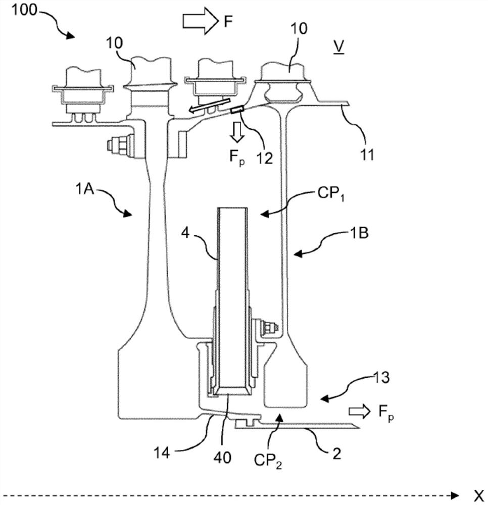
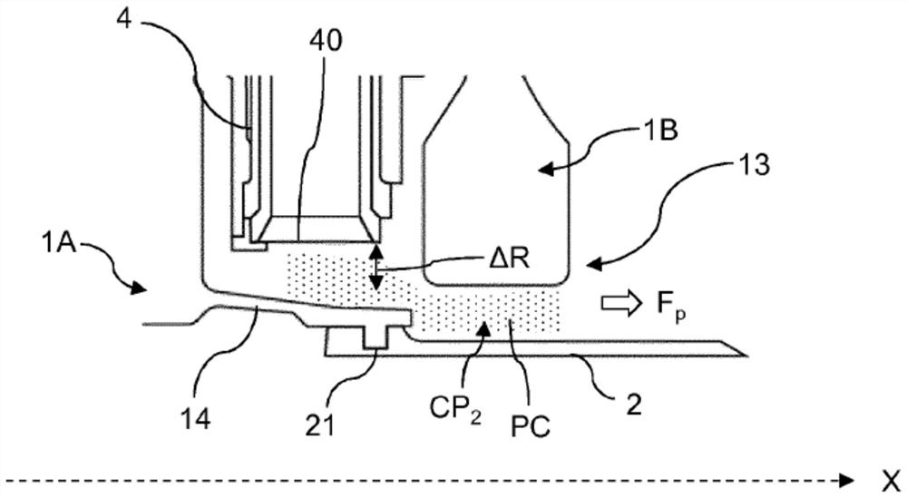
[0041] refer to Figure 4 , in a known manner, the compressor 100 comprises an upstream compressor disk 1A, a downstream compressor disk 1B and a gas flow collec...


PUM


Abstract

The invention relates to a turbine engine extending longitudinally along an X axis and including a main duct (V) in which an air stream (F) flows, the turbine engine including at least one upstream compressor disc (1A), at least one downstream compressor disc (1B) and a circuit for collecting air from an air stream (FP) collected in the main duct, the air collection circuit including a radial portion (CP1) in which at least one air collection tube (4) is mounted and a longitudinal portion (CP2) extending between a cylindrical body (5) and a central bore (13) of the downstream compressor disc.The turbine engine includes a plurality of blades (6) extending in the longitudinal portion of the air collection circuit, configured to be rotated about the X axis, in order to rotate the collected air stream (FP).

Description

technical field [0001] The present invention relates to a turbomachine and a method of collecting a gas flow in a turbomachine. Background technique [0002] refer to figure 1 , in a known manner, the turbine T extends longitudinally along the X-axis and enables the flow F in the annular main duct V from upstream to downstream. Hereinafter, the terms "upstream" and "downstream" are defined with respect to the X-axis extending from upstream to downstream. The terms "longitudinal" and "radial" are defined with respect to the X-axis, the term "radial" is more specifically defined in a plane transverse to the X-axis. Similarly, the terms "inner" and "outer" are defined radially with respect to the X-axis. [0003] The turbine T includes a compressor 100, a combustor and a turbine in which an airflow F flows from upstream to downstream. The compressor 100 comprises a plurality of compressor discs in a known manner. Such as figure 2 As shown, the turbine includes a gas flow...

Claims


Application Information

Patent Timeline
IPC IPC(8): F04D29/32F04D29/58F01D5/00
CPCF01D5/082F01D11/001F02C6/08F04D29/321F04D29/582F05D2240/126F01D5/12F05D2260/20
Inventor 克里斯多夫·斯科尔特斯于利斯·雅克·伯纳德·丹特尼
Owner SAFRAN AIRCRAFT EGINES
Why Eureka
Try Eureka