A pipe fitting crimping device

A technology of pipe fittings and components, which is applied in the direction of lifting devices, tubular objects, household appliances, etc., can solve the problems of unstable crimping device position, poor crimping effect, and difficulty in placing pipe fittings, and achieve good crimping effect, extended service life, and easy operation Labor-saving effect

Active Publication Date: 2022-01-21
安徽昱鑫金属制品有限公司
View PDF7 Cites 0 Cited by
  • Summary
  • Abstract
  • Description
  • Claims
  • Application Information

AI Technical Summary

Problems solved by technology

This crimping machine has certain limitations, and can only be used in fixed workshops and other places, and is not suitable for use in the field, and the flexibility of use is poor
[0003] Therefore, there is a new crimping structure that is more flexible to use. For example, a pipe crimping device disclosed in Chinese Patent Application No. 202010565509.6 includes an outer positioning frame. An array of arc-shaped extrusion modules distributed at intervals, all of the arc-shaped extrusion modules surround and form a crimping space for pipe fittings to be inserted, all of the arc-shaped extrusion modules are installed in the outer positioning frame for all the arc-shaped extrusion The module forms an inner movable elastic zooming surrounding frame for buckling space zooming, and the outer positioning frame is provided with a linear propulsion mechanism that drives the inner movable elastic zooming surrounding frame zooming in the front and back direction to drive the buckling space zooming. This structure is used in the field or other places with harsh conditions such as mountainous areas, but because the operation is hand-held, it is difficult to lay the pipe flat, and when two hands are used, the main part of the crimping mechanism is held by one hand , when the other hand operates the movable handle with force, the whole device will be unstable, and the position of the crimping device in the pipe fitting will be unstable, which will cause the crimping effect to deteriorate

Method used


Image

  • A pipe fitting crimping device
  • A pipe fitting crimping device
  • A pipe fitting crimping device

Examples


Embodiment Construction

[0025] The following specific examples are only explanations of the present invention, and it is not a limitation of the present invention. Those skilled in the art can make modifications without creative contribution to the present embodiment as required after reading this specification, but as long as they are within the rights of the present invention All claims are protected by patent law.

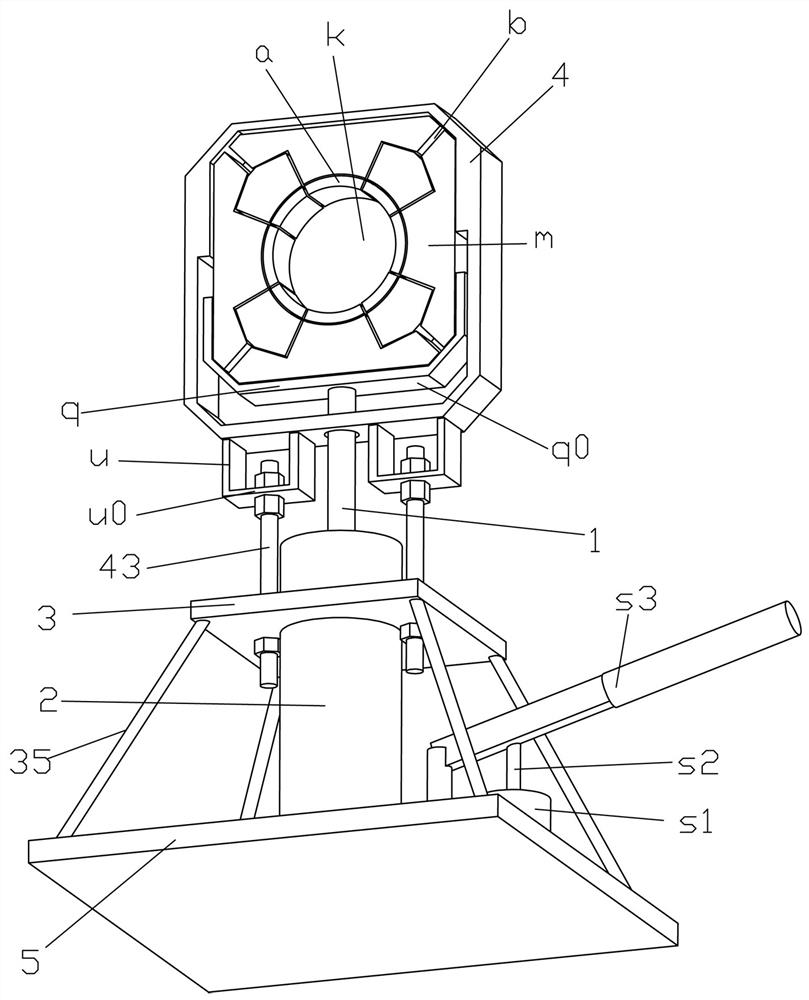
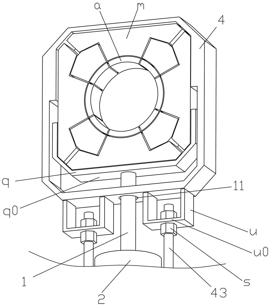
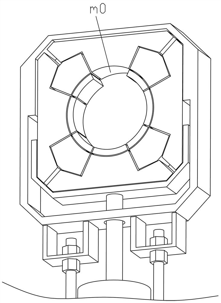
[0026] Examples such as Figure 1-5As shown, a pipe fitting crimping device includes a vertical hydraulic jack and a pipe fitting crimping assembly that is driven upward by the power output piston rod 1 of the hydraulic jack that extends up and down in an upright shape to crimp the pipe. The hydraulic jack applied for is a standing type. This kind of hydraulic jack only needs to adopt the existing structure, but it must be noted that it needs to be a standing type, or an upright type. The power output piston rod 1 is also the jack. The large piston, the power output hydraulic cylinder...


PUM


Abstract

The invention relates to the technical field of pipeline production equipment, in particular to a pipe fitting crimping device, including a hydraulic jack and a pipe fitting crimping assembly, the hydraulic jack has a power output piston rod and a power output hydraulic cylinder body, and the power output hydraulic cylinder body A flat load-bearing plate is fixed on the outer shell of the pipe, and the pipe fitting crimping assembly includes an upright positioning and supporting frame, and more than two arcs arranged in a circumferential array and spaced apart in the supporting and positioning supporting frame. Extrusion modules, all of the arc extrusion modules surround and form a crimping space for pipe fittings to be inserted into, all of the arc extrusion modules are installed on the inner movable elastic zoom enclosure frame located in the positioning support outer frame, the positioning The supporting outer frame is provided with a drive plate that can travel up and down and drive the inner movable elastic zoom to encircle the frame zoom. The lower side of the drive plate is formed with a drive surface for the upper end of the power output piston rod to lean against, and the buckle effect better.

Description

technical field [0001] The invention relates to the technical field of pipeline production equipment, in particular to a pipe fitting crimping device. Background technique [0002] There are various kinds of mechanical structures for crimping existing pipe fittings. Another example is a crimping machine disclosed in Chinese Patent Application No. 201921312168.0, which includes a crimping machine with a box body and a crimping head. The box body is fixedly connected, and the oil inlet pump and the oil storage tank connected with the crimping head pipeline are arranged in the box body, and the drive motor for driving the oil inlet pump is also arranged in the box body, wherein: the box body is provided with a clip Pipe seat, the clamping pipe seat is provided with a clamping groove, the central axis of the clamping groove is coaxial with the central axis of the crimping machine head, and several elastic buckles are arranged on the clamping groove. A buckle groove that coopera...

Claims


Application Information

Patent Timeline
Patent Type & Authority Patents(China)
IPC IPC(8): B21D39/04B29C65/58B66F3/26B66F3/42B29L23/00
CPCB21D39/04B29C65/58B29C66/522B29C66/8286B66F3/26B66F3/42B29L2023/22
Inventor 林高锋陈吉文
Owner 安徽昱鑫金属制品有限公司
Why Eureka
Try Eureka