

Sulfur melting device of carbon disulfide reacting furnace and carbon disulfide reacting furnace
A carbon disulfide, reaction furnace technology, applied in the direction of carbon disulfide, carbon-sulfur compounds, chemical/physical/physical-chemical processes, etc., can solve the problems of poor dispersion, affecting the reaction efficiency, and difficulty in forming, and achieves reduced loss and good gasification effect. , make and maintain simple effects
- Summary
- Abstract
- Description
- Claims
- Application Information
AI Technical Summary
Problems solved by technology
Method used
Image


Examples
Embodiment 1
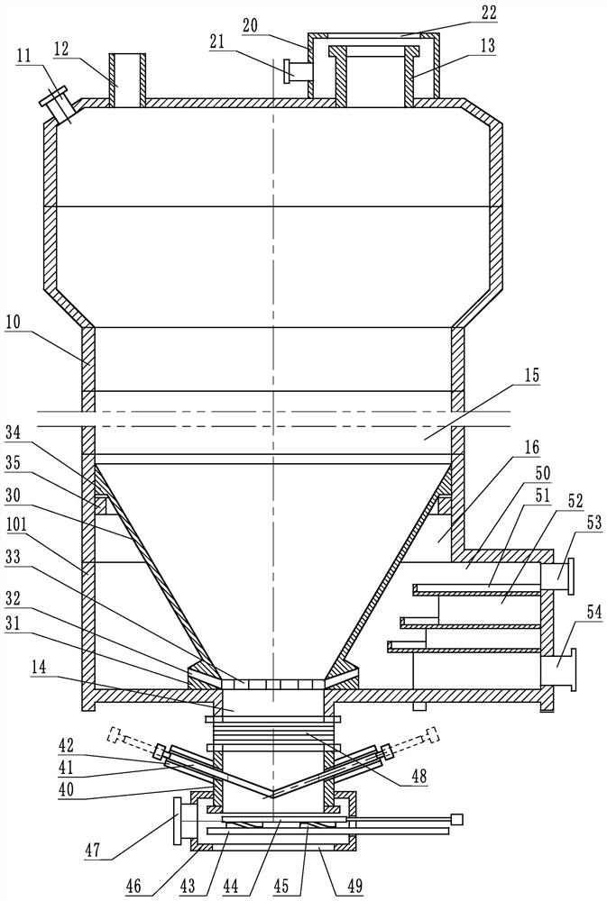
[0031] Embodiment 1: refer to Figure 1 ~ Figure 4 , is a structural schematic diagram of Embodiment 1 of the present invention, including a furnace body 10, a feed port 13, a discharge port 12 and a slag discharge port 14. The furnace body 10 is composed of multiple sections, at least divided into upper, middle and lower sections , the lower section is a sulfurization device, the feed port 13 and the discharge port 12 are arranged on the upper section of the furnace body 10, and the furnace body is also provided with a thermometer interface 11.
[0032] One of the feed port 13 or the slag discharge port 14 is provided with a feed dust collection device 20, which is a cover body arranged outside the feed port 13 or the slag discharge port 14, and the cover body is provided with a feed smoke dust collector. The side port 21 of the collecting device and the straight port 22 of the feeding fume collecting device, the side port 21 of the feeding fume collecting device is a negativ...
Embodiment 2
[0041] Embodiment 2: refer to Figure 5 , is a schematic structural diagram of Embodiment 2 of the present invention. Compared with Embodiment 1, the difference of this embodiment is that: the edge of the sulfurization platform 51 is provided with a sawtooth-shaped sulfur distribution port 55, which can make the addition of a sulfuration mechanism It is even more important for the sulfur to be evenly distributed during the liquefaction process.
Embodiment 3
[0042] Embodiment 3: refer to Figure 6 , is a structural schematic diagram of Embodiment 3 of the present invention. Compared with Embodiment 1 or 2, the difference of this embodiment is that the shutter A41 is a flap type: it includes a rotating shaft, and the shutter A41 is arranged on the rotating shaft.
PUM
 Abstract
Description
Claims
Application Information