Optical device, projection optical system, exposure device, and production method for article
An optical device and optical element technology, which is applied in the field of article manufacturing and can solve problems such as light shading and the like
- Summary
- Abstract
- Description
- Claims
- Application Information
AI Technical Summary
Problems solved by technology
Method used
Image

Examples
Embodiment 1
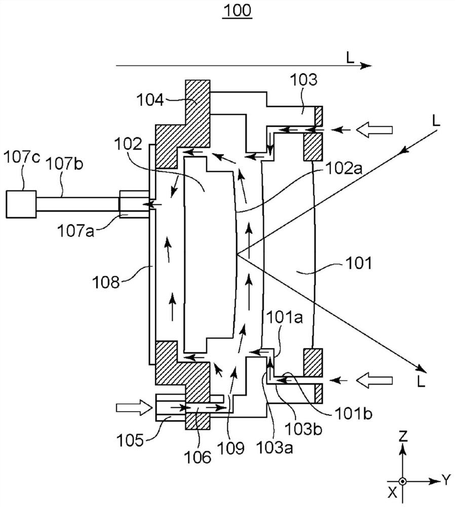
[0025] use figure 2 The optical device 100 of Example 1 will be described. The optical device 100 has a meniscus lens 101 as a first optical element, a convex mirror 102 as a second optical element, a lens barrel 103 as a holding portion for holding the meniscus lens 101, and a lens barrel 103 as a holding portion for holding the convex mirror 102. lens barrel 104 . exist figure 2 In the above, the lens barrel 103 and the lens barrel 104 are configured as independent structures, but the lens barrel 103 and the lens barrel 104 may be integrated to form a single lens barrel.
[0026] In addition, the first optical element is not limited to the meniscus lens 101, and may be a lens of another shape, or may be a mirror. Likewise, the second optical element is not limited to the convex mirror 102, and may be a mirror of another shape, or may be a lens or the like. In addition, the number of optical elements is not limited to two, and the optical device 100 may include three or...
Embodiment 2
[0044] Next, use Figure 4 The structure of the optical device 400 of the second embodiment will be described. In the optical device 400 of the second embodiment, compared with the optical device 100 of the first embodiment, the number of openings provided in the lens barrel 103 is increased. Specifically, the opening 115 is also provided in the vertical direction (Z-axis direction) of the lens barrel 103 . As a result, the amount of gas sucked from the outer space of the lens barrels 103, 104 to the inner space increases, so that the cooling force of the lens barrels 103, 104, the meniscus lens 101, and the convex mirror 102 can be further enhanced.
Embodiment 3
[0046] Next, use Figure 5 The structure of the optical device 500 of the third embodiment will be described. In the optical device 500 of the third embodiment, the arrangement of the gas discharge unit 107 of the optical device 100 of the first embodiment is different. Specifically, the gas discharge unit 501 is arranged on the upper portion of the convex mirror 102 .
[0047] The gas discharge unit 501 is arranged at a position in the negative direction of the Y-axis with respect to the lens barrel 104 , and discharges gas through an opening provided in the lens barrel 104 . The gas discharge unit 501 includes a connection portion 501a connected to the lens barrel 104, a pipe 501b, and an exhaust mechanism 501c. Through the exhaust action of the exhaust mechanism 501c, the gas is discharged from the inner space of the lens barrels 103, 104 through the pipe 501b. The increase in size of the optical device 500 in the Z-axis direction can be alleviated by arranging the gas di...
PUM
 Abstract
Description
Claims
Application Information
 - R&D
- Intellectual Property
- Life Sciences
- Materials
- Tech Scout
- Unparalleled Data Quality
- Higher Quality Content
- 60% Fewer Hallucinations
Browse by: Latest US Patents, China's latest patents, Technical Efficacy Thesaurus, Application Domain, Technology Topic, Popular Technical Reports.
© 2025 PatSnap. All rights reserved.Legal|Privacy policy|Modern Slavery Act Transparency Statement|Sitemap|About US| Contact US: help@patsnap.com