Supercharge Your Innovation With Domain-Expert AI Agents!

Sheath wave barrier for magnetic resonance (MR) applications

A magnetic resonance and barrier technology, which is applied in the directions of using nuclear magnetic resonance spectrum for measurement, using nuclear magnetic resonance image system for measurement, magnetic resonance measurement, etc., can solve problems such as incomplete symmetry

Pending Publication Date: 2021-02-02
SKOPE MAGNETIC RESONANCE TECH AG
View PDF14 Cites 0 Cited by
  • Summary
  • Abstract
  • Description
  • Claims
  • Application Information

AI Technical Summary

Problems solved by technology

Furthermore, structures like the figure-of-eight disclosed in US 5294886 A, due to their imperfect symmetry, do not decouple from the inhomogeneous RF field

Method used


Image

  • Sheath wave barrier for magnetic resonance (MR) applications
  • Sheath wave barrier for magnetic resonance (MR) applications
  • Sheath wave barrier for magnetic resonance (MR) applications

Examples


Embodiment Construction

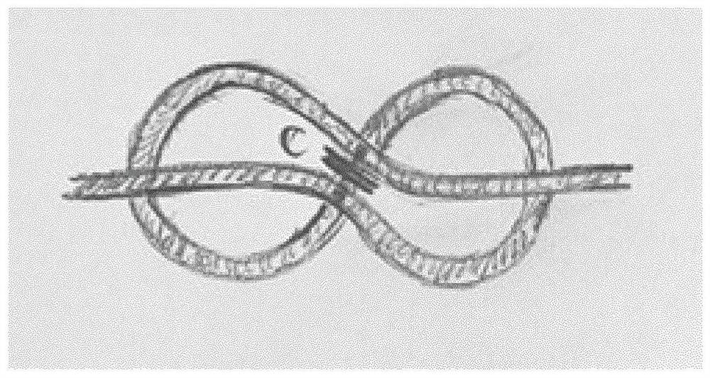
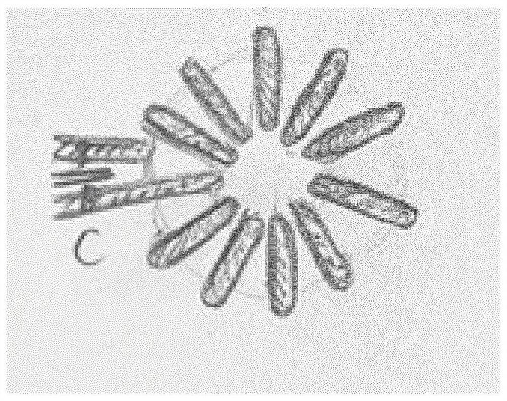
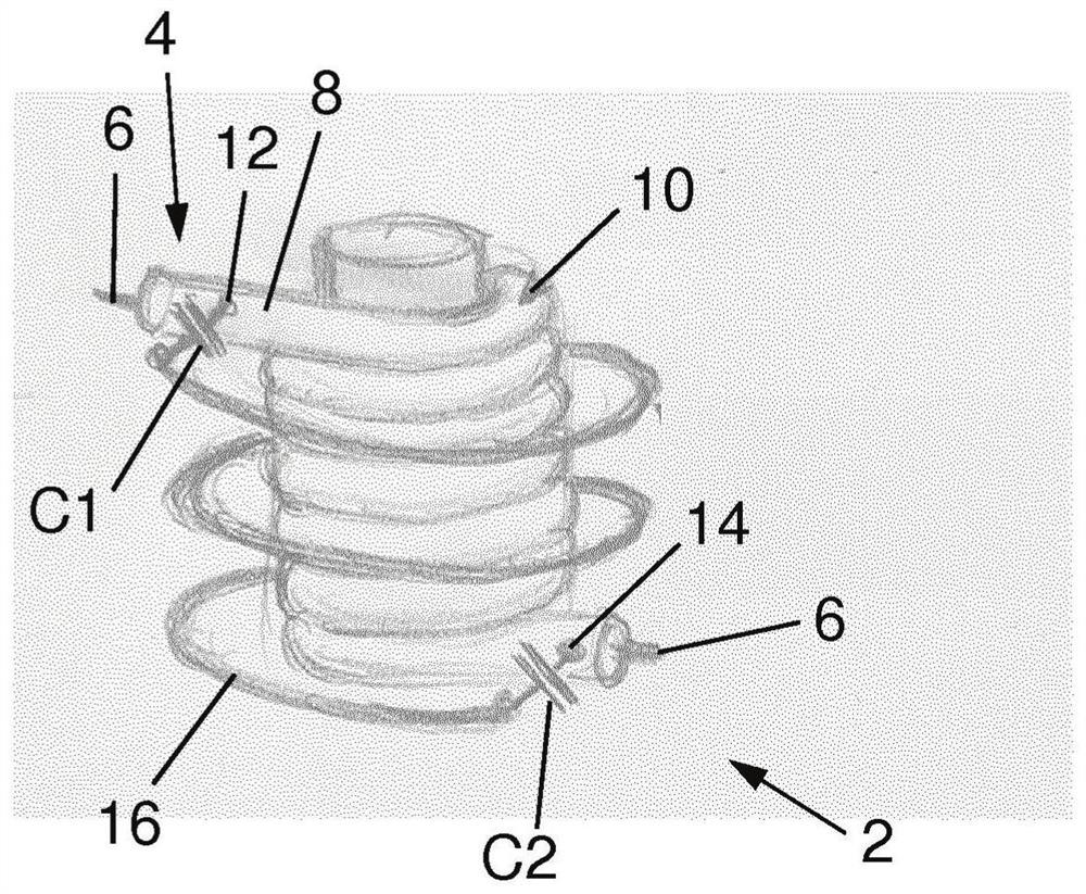
[0068] Figure 2a Shown for use in magnetic resonance (MR) imaging or spectroscopy setups with a predetermined suppression frequency (ω 0 ) A sheath wave barrier 2 that suppresses the electromagnetic RF coupling phenomenon of the cable 4 . The cable 4 is a shielded cable having an inner conductor 6 and a surrounding conductive cable sheath 8 . The sheath wave barrier 2 comprises a section of shielded cable, a primary inductor 10 formed by the shielded cable 4 between a first cable location 12 and a second cable location 14, and a secondary inductor 16 formed by a conductor. In the example shown, the secondary inductor 16 is made of a simple cable arranged concentrically around the primary inductor 10 and is electrically connected to the cable sheath 8 at said first and second cable connections 12 and 14 . Primary inductor 10 and secondary inductor 16 are configured as concentric and substantially coaxial solenoids. To be configured in a compensating manner, the two solenoid...


PUM


Abstract

A sheath wave barrier (2) for suppressing electromagnetic RF coupling phenomena of an electrical cable (4) at a predetermined suppression frequency ([omega]0) in a magnetic resonance (MR) imaging or spectroscopy apparatus, wherein the cable is configured as a shielded cable with at least one inner conductor (6) and a peripherally surrounding electrically conducting cable sheath (8), comprises a segment of said shielded cable and a primary inductor formed from said shielded cable segment between a first cable location (12) and a second cable location (14). A secondary inductor (16) formed by aconductor is concentrically arranged within or around the primary inductor between said first and second cable locations. The secondary inductor is electrically connected to the cable sheath at said first and second cable connections over respective first and second RLC network members (M1, M2), the primary and secondary inductors being configured in compensating manner such that magnetic field generated by said primary and secondary inductors is substantially cancelled in any region surrounding the sheath wave barrier.

Description

technical field [0001] The present invention generally relates to a sheath wave barrier for suppressing electromagnetic RF coupling phenomena of cables in MR devices. Background technique [0002] The operation of MR devices, including but not limited to MR imaging (MRI), creates a hostile electromagnetic environment for any equipment used in the vicinity of the imaging volume. Such equipment must withstand strong magnetic fields and high-power radio-frequency (radio-frequency, RF) pulses. [0003] Any cables running within the scanner bore of the MRI apparatus are prone to interact with the RF field, causing surface currents on the cable shield. These currents have many adverse effects: [0004] - in the vicinity of the patient, they can produce excessive energy absorption in human tissue, potentially causing tissue burns; [0005] - RF power can flow out of the hole along the cable; [0006] - the current on the cable changes the RF field distribution inside the hole; ...

Claims


Application Information

Patent Timeline
Patent Type & Authority Applications(China)
IPC IPC(8): G01R33/36G01R33/565G01R33/58
CPCG01R33/3685G01R33/56518G01R33/34092G01R33/38G01R33/46G01R33/48H01B11/1895
Inventor T.施密德D.O.布鲁纳
Owner SKOPE MAGNETIC RESONANCE TECH AG
Features
  • R&D
  • Intellectual Property
  • Life Sciences
  • Materials
  • Tech Scout
  • Unparalleled Data Quality
  • Higher Quality Content
  • 60% Fewer Hallucinations
Learn More