Monopole parallel filter-pressing type electrolytic cell for electrochemical fluorination
An electrochemical and electrolytic cell technology, applied in the field of electrochemical fluorination unipolar parallel filter press electrolytic cells, to achieve the effects of convenient maintenance, ensuring zero spacing and improving electrolysis efficiency
- Summary
- Abstract
- Description
- Claims
- Application Information
AI Technical Summary
Problems solved by technology
Method used
Image

Examples
Embodiment 1
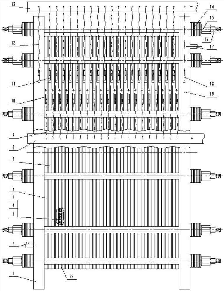
[0028] A kind of electrochemical fluorination monopolar parallel pressure filter electrolyzer, such as figure 1 As shown, an electrochemical fluorination monopolar parallel filter press electrolyzer includes a tank body, and the tank body is provided with a relatively parallel left end plate 1 and a right end plate 19, and the left end plate 1 and the right end plate The electrolysis area between the plates 19 is provided with a plurality of relatively parallel pull rods 16, and the two ends of the pull rods 16 are locked and fixed on the left end pole plate 1 and the right end pole plate 19 by disc springs 14 and fastening nuts 15; Some anode plates 6 and some cathode plates 7 are arranged between the pole plate 1 and the right end pole plate 19, the anode plates 6 and the cathode plates 7 are alternately arranged, and the left end pole plate 1, some anode plates 6, some cathode plates 7, the right end The pole plates 19 are distributed side by side and are fixed by means of ...
Embodiment 2
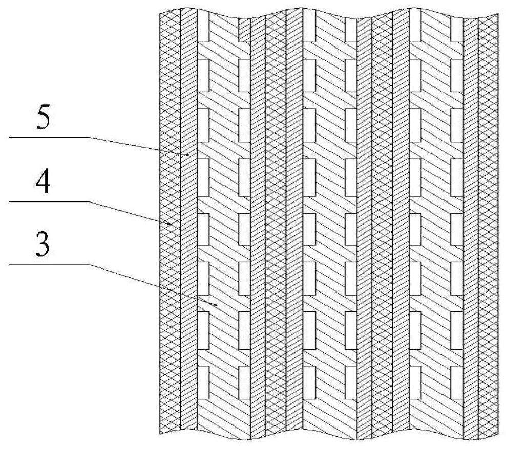
[0037] The structure of this embodiment is basically the same as that of Embodiment 1, and the difference is that when the material generated by the electrolysis cathode and anode is relatively inert, the cathode plate 7, the secondary electrode catalyst plate 5, The anode plates 4 are pressed against each other and prevent short circuits. After the diaphragm 4 is removed, there is no diaphragm resistance in the electrolytic cell, which saves more power and energy. At the same time, the structure of the cell body is simpler and more compact, and the maintenance is more convenient.
Embodiment 3
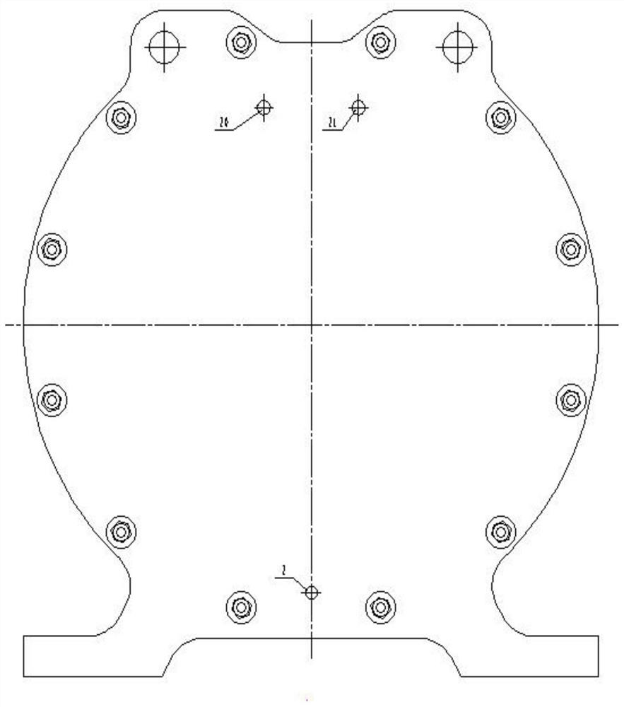
[0039] The structure of this embodiment is basically the same as that of Embodiment 1, and the difference is that: the left end plate 1, the anode plate 6, the cathode plate 7, and the right end plate 19 are all as follows Figure 4 square as shown. Since most of the nickel plates provided by the supplier are square, a large amount of expensive nickel plates will be wasted if they are processed into a round shape. Therefore, the electrolytic cell is directly set to a square shape to reduce the waste of nickel plates.
[0040] The number of the pull rods 16 is 4-20, which are evenly distributed and fixed along the left end pole plate 1 and the right end pole plate 19.
PUM
 Abstract
Description
Claims
Application Information
 - Generate Ideas
- Intellectual Property
- Life Sciences
- Materials
- Tech Scout
- Unparalleled Data Quality
- Higher Quality Content
- 60% Fewer Hallucinations
Browse by: Latest US Patents, China's latest patents, Technical Efficacy Thesaurus, Application Domain, Technology Topic, Popular Technical Reports.
© 2025 PatSnap. All rights reserved.Legal|Privacy policy|Modern Slavery Act Transparency Statement|Sitemap|About US| Contact US: help@patsnap.com