Aero-engine, intake valve and intake structure of aero-engine
A technology of aero-engine and air intake structure, which is applied in the direction of engine components, machine/engine, turbine/propulsion device air intake, etc. It can solve the problems of poor adjustability of gas throttle, complex structure design, high cost, etc., and achieve the purpose of improving the engine Performance, compact structure, optimized combustion effect
- Summary
- Abstract
- Description
- Claims
- Application Information
AI Technical Summary
Problems solved by technology
Method used
Image

Examples
Embodiment 1
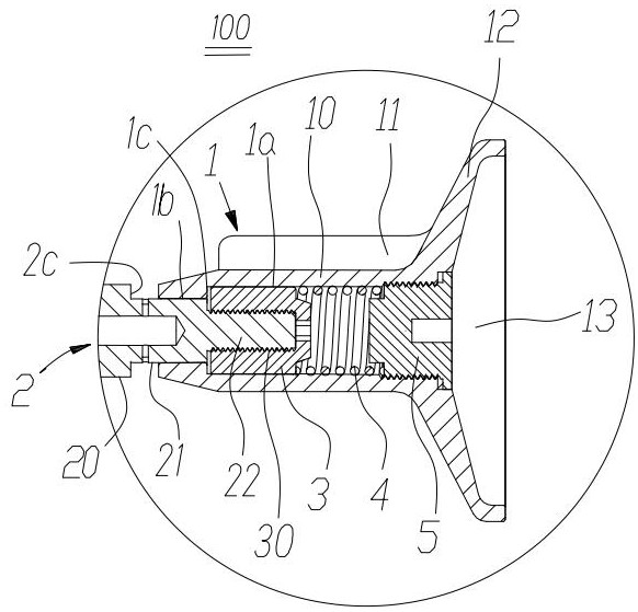
[0024] like figure 1 As shown, the present embodiment provides an air intake valve of an aero-engine, which includes: an air intake seat 1 , an air intake rod 2 , a joint sleeve 3 , an elastic member 4 and a position-limiting plug 5 .
[0025] The air intake seat 1 has a cavity structure extending from the right end surface of the air intake seat 1 to the left end surface. The cavity structure includes a large cavity 1a away from the intake rod 2 and a small cavity 1b close to the intake rod 2, and a step 1c is formed at the junction of the large cavity 1a and the small cavity 1b. The joint sleeve 3, the elastic member 4 and the position-limiting plugging head 5 are loaded into the large cavity 1a sequentially and in contact with each other. The elastic member 4 can be a spring, preferably a recoil spring; the limiting plug 5 can be a blocking screw.
[0026] The intake rod 2 includes a large rod body 20 and a small rod body 21 , and a step 2c is formed at the connection bet...
Embodiment 2
[0031] like figure 1 As shown, the present embodiment provides an air intake valve of an aero-engine, which includes: an air intake seat 1 , an air intake rod 2 , a joint sleeve 3 , an elastic member 4 and a position-limiting plug 5 .
[0032] The air intake seat 1 has a cavity structure extending from the right end surface of the air intake seat 1 to the left end surface. The cavity structure includes a large cavity 1a away from the intake rod 2 and a small cavity 1b close to the intake rod 2, and a step 1c is formed at the junction of the large cavity 1a and the small cavity 1b. The joint sleeve 3, the elastic member 4 and the position-limiting plugging head 5 are loaded into the large cavity 1a sequentially and in contact with each other. The elastic member 4 can be a spring, preferably a recoil spring; the limiting plug 5 can be a blocking screw.
[0033] The intake rod 2 includes a large rod body 20 and a small rod body 21 , and a step 2c is formed at the connection bet...
Embodiment 3
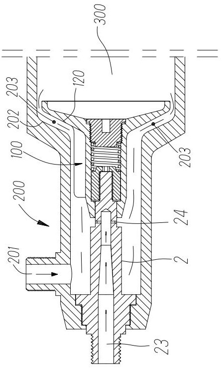
[0039] like figure 1 and figure 2 As shown, the present embodiment provides an air intake structure of an aero-engine, which comprises: an intake valve 100 and an oil-air mixing cavity formed by the tube wall 200 of the oil-air mixing cavity, and the intake valve 100 is set in the oil-gas mixing cavity.
[0040] The intake valve 100 includes: an intake seat 1 , an intake rod 2 , a joint sleeve 3 , an elastic member 4 and a position-limiting plug 5 . The air intake seat 1 has a cavity structure extending from the right end surface of the air intake seat 1 to the left end surface. The cavity structure includes a large cavity 1a away from the intake rod 2 and a small cavity 1b close to the intake rod 2, and a step 1c is formed at the junction of the large cavity 1a and the small cavity 1b. The joint sleeve 3, the elastic member 4 and the position-limiting plugging head 5 are loaded into the large cavity 1a sequentially and in contact with each other. The elastic member 4 can...
PUM
 Abstract
Description
Claims
Application Information
 - R&D
- Intellectual Property
- Life Sciences
- Materials
- Tech Scout
- Unparalleled Data Quality
- Higher Quality Content
- 60% Fewer Hallucinations
Browse by: Latest US Patents, China's latest patents, Technical Efficacy Thesaurus, Application Domain, Technology Topic, Popular Technical Reports.
© 2025 PatSnap. All rights reserved.Legal|Privacy policy|Modern Slavery Act Transparency Statement|Sitemap|About US| Contact US: help@patsnap.com