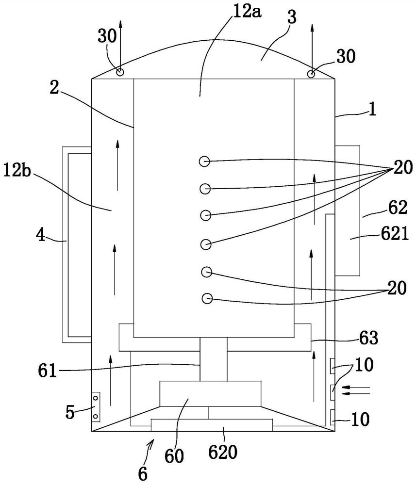
Dehydration device provided with centrifugal dehydration assembly and used for tin powder

A technology of centrifugal dehydration and dehydration device, which is applied in the direction of heating device, lighting and heating equipment, drying solid materials, etc. It can solve the problems of low dehydration efficiency, incomplete dehydration, and inability to quickly realize dehydration, and achieve high efficiency and fast dehydration speed Effect

Inactive Publication Date: 2021-02-12
广东天高科技有限公司
View PDF0 Cites 0 Cited by
  • Summary
  • Abstract
  • Description
  • Claims
  • Application Information

AI Technical Summary

Problems solved by technology

The existing problem is: when the dehydration device with the aforementioned structure is used to dehydrate the tin powde

Method used


Image

  • Dehydration device provided with centrifugal dehydration assembly and used for tin powder

Examples


Example Embodiment

[0014]The following specific examples illustrate the implementation of the present invention. Those skilled in the art can easily understand other advantages and effects of the present invention from the content disclosed in this specification.

[0015]It should be noted that the structure, ratio, size, etc. shown in the drawings of this specification are only used to match the content disclosed in the specification for people familiar with this technology to understand and read, and are not used to limit the implementation of the present invention. Therefore, it has no technical significance. Any structural modification, proportional relationship change, or size adjustment should still fall within the scope of the present invention without affecting the effects and objectives that can be achieved by the present invention. The technical content can cover the range. At the same time, terms such as "upper", "lower", "left", "right", "middle" and "one" cited in this specification are only...


PUM


Abstract

The invention provides a dehydration device provided with a centrifugal dehydration assembly and used for tin powder. The dehydration device comprises an outer barrel, an inner barrel, a flip cover, ahandle and a power transmission base, wherein the centrifugal dehydration assembly comprises a rotating motor, a rotating shaft, a control part and a heating disc, the heating disc is arranged on theouter side wall of the bottom of the inner barrel and electrically connected with the control part, and a plurality of dehydration holes which are longitudinally arranged at intervals are formed in the side wall of the inner barrel; and the control part comprises a circuit board arranged at the bottom of the outer barrel and a control panel, a housing part of the control panel is fixed to the side wall of the outer barrel, a signal transmission part of the control panel and a conductive part of the rotary motor are electrically connected to the circuit board, an annular gap is formed betweenthe inner side wall of the outer barrel and the outer side wall of the inner barrel, a plurality of air outlets are formed in the flip cover above the annular gap, a plurality of air inlets are formedin the side wall of the outer barrel below the control panel, and the air inlets, the annular gap and the air outlets form an air flow channel. By arranging the centrifugal dehydration assembly, heating and dehydration are achieved at the same time, the tin powder dehydration is high in speed, thorough, and high in efficiency.

Description

technical field [0001] The invention relates to a dehydration device for tin powder provided with a centrifugal dehydration assembly. Background technique [0002] At present, there is a dehydration device in the prior art, which includes an outer barrel, an inner barrel, a flip cover, a handle, and a power transmission seat. Both the outer barrel and the inner barrel have an upper opening, and the flip cover is pivotally connected to the top of the outer barrel. The upper opening of the outer barrel and the upper opening of the inner barrel. The existing problem is: when the dehydration device with the aforementioned structure is used to dehydrate the tin powder, the dehydration cannot be achieved quickly and the dehydration is not complete, resulting in low dehydration efficiency. [0003] Therefore, the present invention provides a dehydration device for tin powder provided with a centrifugal dehydration assembly. Contents of the invention [0004] In view of the abov...

Claims


Application Information

Patent Timeline
IPC IPC(8): F26B11/08F26B23/00F26B25/00F26B25/10
CPCF26B11/08F26B23/00F26B25/00F26B25/10
Inventor 张锦镜
Owner 广东天高科技有限公司
Why Eureka
Try Eureka