Supercharge Your Innovation With Domain-Expert AI Agents!

Organic waste gas purification device

A purification device and organic waste gas technology, applied in the direction of gas treatment, transportation and packaging, chemical instruments and methods, etc., can solve the problems of increased floor area, cumbersome waste gas treatment, low efficiency, etc., and achieve the effect of improving the processing speed

Pending Publication Date: 2021-02-26
中科蓝(福建)环保科技有限公司
View PDF5 Cites 0 Cited by
  • Summary
  • Abstract
  • Description
  • Claims
  • Application Information

AI Technical Summary

Problems solved by technology

[0002] Existing industrial waste gas treatment equipment often uses UV photolysis purifiers and activated carbon adsorption towers in waste gas treatment projects, but since most of the UV photolysis purifiers and activated carbon adsorption towers are split, split equipment not only increases The floor space also increases the cumbersomeness of waste gas treatment. For this reason, an integrated multi-stage waste gas treatment device emerged as the times require. However, the existing industrial waste gas treatment devices have low processing efficiency, and the power basis for treating waste gas lies in the final stage. The suction drives the industrial waste gas to be purified step by step. At the same time, the industrial waste gas contains large particles of dust and other substances that will block the filter screen. For industrial waste gas with large particles of dust and debris, it is often necessary to stop the machine to clean the filter screen. The use effect is not good and the efficiency is low. , it is urgent to develop an organic waste gas purification device that can quickly and effectively treat industrial waste gas

Method used


Image

  • Organic waste gas purification device

Examples


Embodiment Construction

[0010] The present invention will be further described in conjunction with the accompanying drawings and specific embodiments.

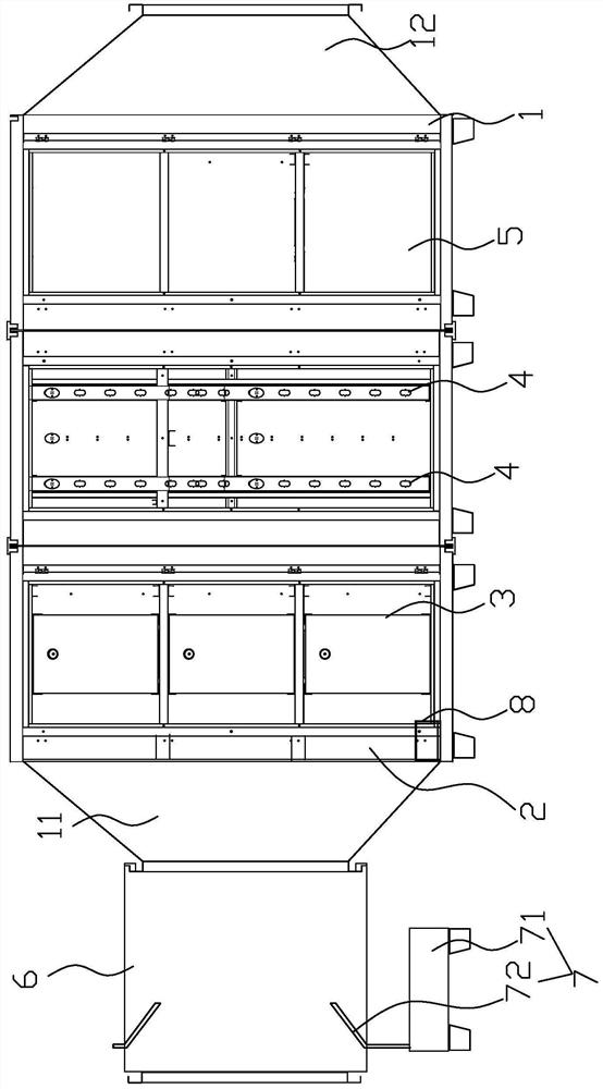
[0011] refer to figure 1 , the preferred organic waste gas purification device of the present invention includes a box body 1, a large particle filter assembly 2, a first activated carbon filter assembly 3, a second activated carbon filter assembly 4, a UV photolysis assembly 5, a suction fan, a connecting pipe 6, a blower Gas mechanism 7 and vibrator 8, the box body 1 is divided into three spaces in turn from left to right, and the left side is the exhaust gas inlet 11, and the right side is the discharge outlet 12, and the large particle filter assembly 2 includes a plurality of filter cotton And the first grid frame for accommodating multiple pieces of filter cotton, the multiple pieces of filter cotton are filled in the first grid frame, the first grid frame is vertically arranged in the box body 1 at the exhaust gas inlet 11 on the left side, th...


PUM


Abstract

The invention relates to the technical field of industrial waste gas treatment, and provides an organic waste gas purification device. The device comprises a box body, a large-particle filtering assembly, a first activated carbon filtering assembly, a second activated carbon filtering assembly, an UV photolysis assembly, a suction fan, a connecting pipe, a blowing mechanism and a vibrator, whereinthe large particle filtering assembly is arranged at an inlet of the box body; the first activated carbon filtering assembly, the UV photolysis assembly and the second activated carbon filtering assembly are sequentially arranged in three spaces, from left to right, of the box body; the free end of each air blowing pipe penetrates through a through hole of the connecting pipe to extend into the connecting pipe; the air outlet end of each air blowing pipe faces the waste gas inlet of the box body; an included angle formed between the part, located in the connecting pipe, of each air blowing pipe and the inner wall of the connecting pipe is 20-70 degrees; and the vibrator is arranged in the box body and located at the bottom of the large-particle filtering assembly. The organic waste gas purification device overcomes the problems that an existing organic waste gas purification device is inconvenient to use and low in treatment effect are solved.

Description

technical field [0001] The invention relates to the technical field of industrial waste gas treatment, in particular to an organic waste gas purification device. Background technique [0002] Existing industrial waste gas treatment equipment often uses UV photolysis purifiers and activated carbon adsorption towers in waste gas treatment projects, but since most of the UV photolysis purifiers and activated carbon adsorption towers are split, split equipment not only increases The floor space also increases the cumbersomeness of waste gas treatment. For this reason, an integrated multi-stage waste gas treatment device emerged as the times require. However, the existing industrial waste gas treatment devices have low processing efficiency, and the power basis for treating waste gas lies in the final stage. The suction drives the industrial waste gas to be purified step by step. At the same time, the industrial waste gas contains large particles of dust and other substances that...

Claims


Application Information

Patent Timeline
IPC IPC(8): B01D46/00B01D53/00B01D53/74B01D53/44
CPCB01D46/0036B01D53/007B01D53/74B01D53/44B01D2258/02B01D2253/102B01D2259/804B01D2257/91B01D46/56B01D46/76
Inventor 陈晓东
Owner 中科蓝(福建)环保科技有限公司
Features
  • R&D
  • Intellectual Property
  • Life Sciences
  • Materials
  • Tech Scout
  • Unparalleled Data Quality
  • Higher Quality Content
  • 60% Fewer Hallucinations
Learn More