DLP projector, optical machine and LED light source device calibration method
A technology of LED light source and calibration method, applied in projection devices, optics, instruments, etc., can solve problems affecting projection uniformity and projection quality, affecting projector volume, cost, uncontrollable tolerances, etc., to improve projection uniformity and The effect of projecting quality, improving energy utilization and reducing positioning error
- Summary
- Abstract
- Description
- Claims
- Application Information
AI Technical Summary
Problems solved by technology
Method used
Image

Examples
Embodiment Construction
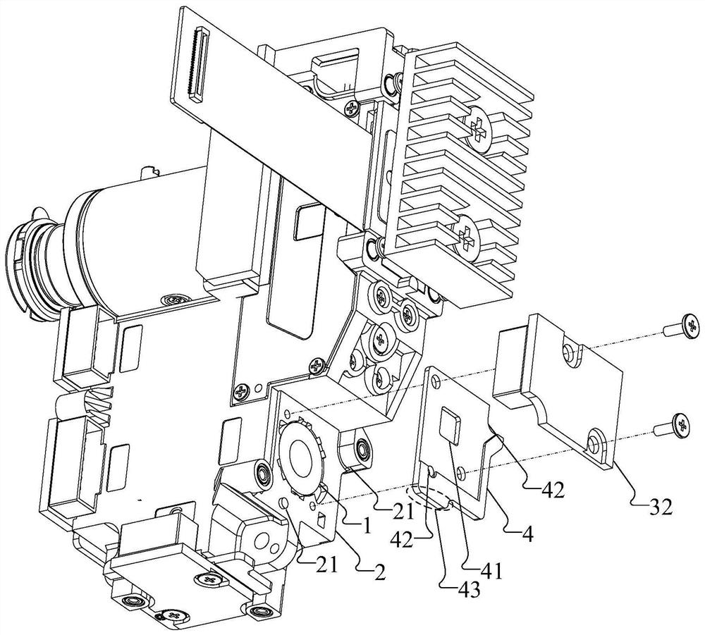
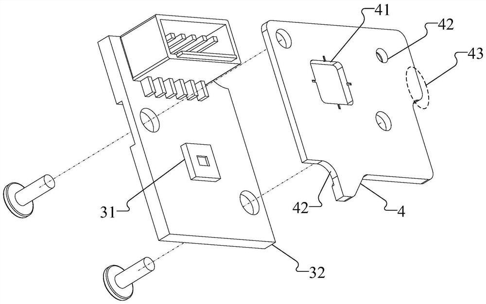
[0032] In a DLP projector, in order to improve the energy utilization rate of the light source, improve projection uniformity and projection quality, this embodiment discloses a method for calibrating an LED light source device for a DLP projector. The DLP projector includes an optical machine. Please refer to figure 1 with figure 2 ,in, figure 1 It is a schematic diagram of the optical machine structure of a DLP projector disclosed in this embodiment, figure 2It is a schematic exploded view of a PCB board and LED bracket installation structure disclosed in this embodiment. In a specific embodiment, the optical machine includes a collimating lens 1, a collimating lens mount 2 and an LED light source device, wherein the LED light source device includes : LED light-emitting chip 31 and LED bracket 4, wherein, LED light-emitting chip 31 is fixed on the LED bracket 4 through PCB board 32.
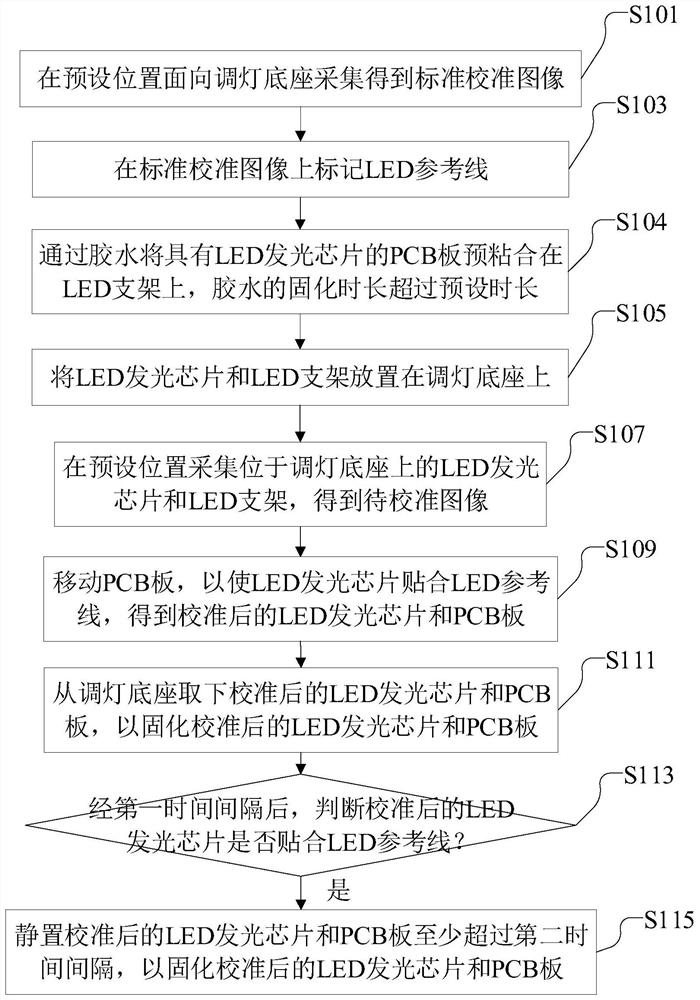
[0033] Please refer to image 3 , is a flow chart of a method for calibrating an LED l...
PUM
 Abstract
Description
Claims
Application Information
 - Generate Ideas
- Intellectual Property
- Life Sciences
- Materials
- Tech Scout
- Unparalleled Data Quality
- Higher Quality Content
- 60% Fewer Hallucinations
Browse by: Latest US Patents, China's latest patents, Technical Efficacy Thesaurus, Application Domain, Technology Topic, Popular Technical Reports.
© 2025 PatSnap. All rights reserved.Legal|Privacy policy|Modern Slavery Act Transparency Statement|Sitemap|About US| Contact US: help@patsnap.com