Household door mat cleaning device
A cleaning device and doormat technology, applied in the direction of cleaning methods using tools, cleaning methods and utensils, chemical instruments and methods, etc., can solve the problems of difficult cleaning of doormat mud and large water consumption, and reduce water waste , Intensify the vibration, increase the speed effect
- Summary
- Abstract
- Description
- Claims
- Application Information
AI Technical Summary
Problems solved by technology
Method used
Image

Examples
Embodiment 1
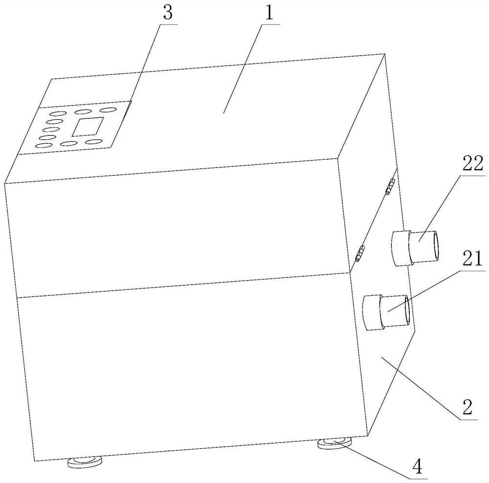
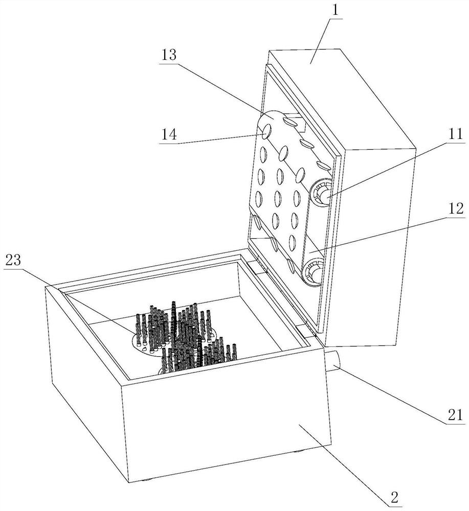
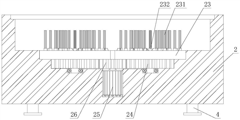
[0030] like figure 1 - Figure 9 As shown, the present invention provides a household doormat cleaning device, comprising an end cover 1, a control panel 3 is arranged in the middle of one side of the upper end of the end cover 1, and the side of the lower end of the end cover 1 away from the control panel 3 is hinged The chassis 2 is movably connected, and the four corners of the lower end of the chassis 2 are fixedly connected with support feet 4. The inside of the end cover 1 is provided with a transmission wheel 12, and the outer side of the transmission wheel 12 is connected with a transmission belt 13. The transmission belt 13 is far away from the transmission. One end of the wheel 12 is provided with a rubber sucker 14 , and the inside of the chassis 2 is provided with a brush plate 23 , and the end surface of the transmission belt 13 is attached to the upper end surface of the brush plate 23 .
[0031] In this embodiment, through the setting of the rubber suction cup ...
Embodiment 2
[0035] like figure 2 , Figure 5 , Figure 7-9 As shown, on the basis of Embodiment 1, the present invention provides a technical solution: both sides of the inside of the end cover 1 are fixedly connected with load-bearing frames 11, and the number of load-bearing frames 11 arranged on one side of the inside of the end cover 1 Both ends of the transmission wheel 12 are movably connected with the load-bearing frame 11, the inside of the transmission wheel 12 is provided with a support shaft 121, and a support frame 16 is fixedly connected between the inner wall of the transmission wheel 12 and the outer wall of the support shaft 121. The number of support frames 16 set between the drive wheel 12 and the support shaft 121 is three, and the three support frames 16 are evenly distributed between the drive wheel 12 and the support shaft 121. The inside of the drive wheel 12 is provided with a hub motor 15, and the hub motor The shell of 15 is fixedly connected with the inner wa...
Embodiment 3
[0038] like Figure 7 As shown, on the basis of Example 2, the present invention provides a technical solution: preferably, the slope of the No. 1 drainage block 122 is provided with a pressure groove 1221, and the diameter of the upper end of the pressure groove 1221 is smaller than the diameter of the lower end.
[0039] In this embodiment, through the setting of the pressure groove 1221 and the rotation of the transmission wheel 12, the flowing water can be squeezed by the pressure groove 1221 to form a water flow with a high impact force, and then through the rotation of the transmission wheel 12, The water flow is ejected in a spiral shape, and the water flow with higher impact is intermittently impacted on the vibrating paddle 123 and the support frame 16, so that the impact received by the support frame 16 and the vibrating paddle 123 is intermittently increased, so that the support frame 16 and the vibration of the vibrating plectrum 123 increases.
PUM
 Abstract
Description
Claims
Application Information
 - R&D Engineer
- R&D Manager
- IP Professional
- Industry Leading Data Capabilities
- Powerful AI technology
- Patent DNA Extraction
Browse by: Latest US Patents, China's latest patents, Technical Efficacy Thesaurus, Application Domain, Technology Topic.
© 2024 PatSnap. All rights reserved.Legal|Privacy policy|Modern Slavery Act Transparency Statement|Sitemap