Mounting base, battery and electric equipment
A mounting seat and battery technology, which is applied in the field of batteries, electrical equipment, and mounting seats, can solve problems such as safety needs to be improved, battery short circuit, etc., and achieve the effect of not being easy to short circuit and improving safety
Active Publication Date: 2021-03-19
CONTEMPORARY AMPEREX TECH CO
10 Cites 2 Cited by
AI-Extracted Technical Summary
Problems solved by technology
[0003]In some cases, the battery is prone to sh...
Method used
Body 51 is provided with diversion groove 511 toward the side of insulator 40, has increased the distance between body 51 and insulator 40 at the position where diversion groove 511 is set, and it is difficult to form liquid between this position and insulator 40. film, so that it is difficult to form a continuous liquid film between the body 51 and the insulator 40, thereby effectively reducing the liquid electrical connection between the output pole 30 and the end plate 10 through the body 51 and the insulator 40, and causing the installation seat 50 to output The risk of insulation protection failure of the pole 30 is reduced, and the battery 100 is less likely to be short-circuited, which improves the safety of the battery 100 .
In some embodiments, please continue to refer to Fig. 4, the body 51 is provided with the drain hole 517 that communicates with the diversion groove 511, the drain hole 517 can discharge the liquid in the diversion groove 511, the liquid diversion groove 511 It is not easy to collect liquid inside, which further reduces the possibility of forming a liquid film between the position where the diversion groove 511 is arranged on the body 51 and the insulating member 40 .
In view of this, the embodiment of the present application provides a kind of technical scheme, on the side of the body of the mounting seat facing the insulator, a diversion groove is set, and the setting of the diversion groove increases the insulation between the body at the position where the diversion groove is set. The distance between the position and the insulator is not easy to form a liquid film, thus effectively reducing the risk of failure of the insulation protection of the mounting seat to the output pole due to the liquid electrical connection between the output pole and the end plate through the body and the insulator .
[0084] Since the flow guide groove 511 runs through both sides of the body 51 in the second direction X, the flow guide groove 511 can divide the liquid film between the body 51 and the insulator 40 (shown in FIG. 3 ) in the first direction The two parts on Z located on both sides of the diversion groove 511 further reduce the possibility of forming a continuous liquid film between the body 51 and the insulator 40 in the first direction Z.
[0087] The first abutting portion 515 and the second abutting portion 516 arranged oppositely in the first direction Z in the body 51 can be used to abut against the insulator 40, which improves the performance of the body 51 after it is installed on the end plate 10. stability.
[0095] In some embodiments, with reference to FIG. 4 and FIG. 5, FIG. 5 is a schematic diagram of installation of the mounting seat 50 and the end plate 10 of the battery 100 shown in FIG. 2. The body 51 of the mountin...
Abstract
The invention provides a mounting base, a battery and electric equipment, and belongs to the technical field of batteries. The mounting base is used for being connected with the end plate and the output electrode, and one side of the end plate is provided with an insulating part used for insulating and isolating the end plate from the single batteries. The mounting base comprises a body, a diversion trench is formed in the side, facing the insulating part, of the body, and the diversion trench is used for preventing the output electrode and the end plate from being electrically connected through liquid between the body and the insulating part. Due to the arrangement of the diversion trench on the body, the distance between the position of the body where the diversion trench is arranged andthe insulating part is increased, and a liquid film is not easy to form between the position and the insulating part, so that a continuous liquid film is not easy to form between the body and the insulating part, and the risk of insulated protection failures caused by the mounting base to the output electrode due to the liquid electric connection between the output electrode and the end plate through the body and the insulating part is effectively reduced; the short circuit phenomenon of the battery is avoided, and the safety of the battery is improved.
Application Domain
Small-sized cells cases/jackets
Technology Topic
Electrical batteryEngineering +4
Image
Examples
- Experimental program(1)
Example Embodiment
[0046] In order to make the objects, technical solutions, and advantages of the present application, the technical solutions in the present application embodiment will be clearly described in connection with the accompanying drawings in the present application embodiment, which is clearly described. Application Serial examples, not all of the embodiments. Based on the embodiments in this application, all other embodiments obtained by those of ordinary skill in the art without creative labor, are the scope of the present application.
[0047]All techniques and scientific terms used in this application are commonly understood from those skilled in the art, unless otherwise defined. The terminology used in the present application is intended to describe specific implementation in the specification of the present application. The purpose of the example is not intended to limit the present application; the terms "of the present application" and "including" and "have" and "have any modifications thereof, intended to cover the inclusion of his inclusion. The specification of the present application and the claims, or the terms "first", "second", "second", or the like in the above drawings are used to distinguish different objects, not to describe a particular order or primary relationship.
[0048] In the present application, "Embodiment" means that the specific features, structures, or characteristics described in connection with the embodiments may be included in at least one embodiment of the present application. This phrase is not necessarily a separate or alternative embodiment of the same embodiment in the various locations in the specification, nor is an independent or alternative embodiment of other embodiments. Those skilled in the art are, and the embodiments described herein can be combined with other embodiments.
[0049] In the description of the present application, it is to be described in that, unless otherwise clear, the term "installation", "connected", "connected", "attachment" should be a generalized understanding, for example, can be a fixed connection, It is also possible to be detachable, or integrally connected; it can be directly connected, or can be interconnected by an intermediate medium, which may be in the interior of the two elements. The specific meaning of the above terms in the present application can be understood in terms of specific cases.
[0050] In the embodiments of the present application, the same reference numerals denote the same components, and for the sake of brevity, in different embodiments, a detailed description of the same components is omitted. It will be appreciated that the thickness, long width of the various components in the present application embodiment, and the integral thickness of the integrated apparatus, and the aspect such as an exemplary statement are only as defined by the present application. .
[0051] The "multiple" appearing in this application refers to more than two (including two).
[0052] In this application, the battery cells may include a lithium ion secondary battery, a lithium ion primary battery, a lithium sulfur battery, a sodium ion battery, a sodium ion battery or a magnesium ion battery, and the like, the present application is not limited thereto. The battery monomer may be cylindrical, flat, rectangular or other shape, etc., the present application is not limited thereto. Battery monomers are generally divided into three types: cylindrical cell monomers, square square battery cells, and soft bag battery cells, the present application is not limited thereto.
[0053] The battery mentioned in the embodiment of the present application refers to a single physical module including one or more battery cells to provide higher voltage and capacity. For example, the battery mentioned in this application can include a battery module or a battery pack. Battery typically include a box for encapsulating one or more battery cells. The box can prevent liquid or other foreign matter to affect charging or discharge of the battery cell.
[0054] The battery cell includes an electrode assembly and an electrolyte, and the electrode assembly consists of a positive electrode sheet, a negative electrode sheet, and a separator. The battery monomer operates mainly from metal ions to move between the positive electrode sheet and the negative electrode sheet. The positive electrode film includes a positive electrode current collector and a positive electrode active material layer, the positive electrode active material layer is coated with the surface of the positive electrode concentration fluid, and the positive electrode concentration fluid of the uncoated positive electrode active material layer protrudes from the positive electrode concentration fluid that has been coated with a positive electrode active material layer. The positive electrode concentration fluid of the uncoated positive electrode active material layer is used as the positive electrode ears. Taking a lithium-ion battery as an example, the material of the positive electrode fluid may be aluminum, and the positive electrode active material may be lithium cobaltate, lithium iron phosphate, three-dimensional lithium or manganese acid. The negative electrode sheet includes an anode current collector and an anode active material layer, the negative electrode active material layer is applied to the surface of the negative electrode fluid, and the negative electrode current collector of the uncoatal active material layer protrudes in the negative electrode fluid that has been coated with an negative electrode active material layer. The negative electrode concentration fluid that is not coated with an negative electrode active material layer is used as a negative electrode ear. The material of the negative electrode fluid may be copper, the negative electrode active material can be carbon or silicon. In order to ensure that the large current does not blow, the number of positive poles is plural in and laminated together, and the number of negative electrode ears is plural. The material of the isolation membrane can be PP (polypropylene, polypropylene) or PE (polyethylene, polyethylene), and the like. Further, the electrode assembly may be a wound structure, or a laminated structure, and the present application is not limited thereto. The development of battery technology should consider multi-faceted design factors, such as performance parameters such as energy density, cycle life, discharge capacity, charge and discharge ratio, and other, it is necessary to consider the safety of the battery.
[0055] In the cell, generally, the mount is attached to the end plate is attached to the output pole mounting seat, a seat mounted on the mounting seat between the output electrode, and the insulating member against the mounting seat may be provided as an output electrode Insulation protection, the mounting seat will isolate the output electrode with the end plate insulated, and the insulating member is disposed between the battery cell and the end plate, and the insulator is isolated from the end plate insulation.
[0056] The inventors have found that the battery is prone to short-circuit risk. After research, the inventors have found some scenes (such as condensing fields), and liquid is easily attached between the mounting seat and the insulating member, so that the mounting seat is formed between the mounting and insulating members. thin film, likely to cause the output electrode and the end plate by the liquid electrolyte between the connecting member and the insulating mount, the mount thereby causing insulation failure of the output electrode, affect the insulation between the output electrode and the end plate, even Causes the risk of short circuit.
[0057] In view of this, the present application provides a technical solution that provides a flow guide in the mounting body towards one side of the insulator, and the setting of the flow groove increases the distance between the position and the insulator of the body in the position of the body. The liquid film is less likely to form a liquid film between the position and the insulating member, thereby effectively reduces the liquid electrical connection between the output pole and the end plate through the body and the insulating member, resulting in the risk of failure of the installation seat pair of insulation protection.
[0058] The liquid film referred to in the embodiment of the present application is a thin liquid that is staying between the body and the insulating member.
[0059] The technical solution described in this application example is applicable to the battery and the use of a battery using a battery.
[0060] The electrical equipment can be a vehicle, mobile phone, portable device, laptop, ship, spacecraft, electric toys, and electric tools, etc. Vehicles can be fuel vehicles, gas cars or new energy vehicles, new energy vehicles can be pure electric vehicles, hybrid vehicles or increased arcs; spacecraft includes aircraft, rockets, space shutters, spaceships, etc., electric toys include fixed Model or mobile electric toys, for example, game consoles, electric car toys, electric ship toys and electric aircraft toys, etc.; electric tools include metal cutting electric tools, grinding electric tools, assembling electric tools, and railway power tools, for example, Electric drill, electric grinding wheel, electric wrench, electric screwdriver, electric hammer, impact drill, concrete vibrator, etc. The present application examples do not make special restrictions on the above electrical equipment.
[0061] The following examples illustrate the use of electrical equipment as an example for the vehicle as an example.
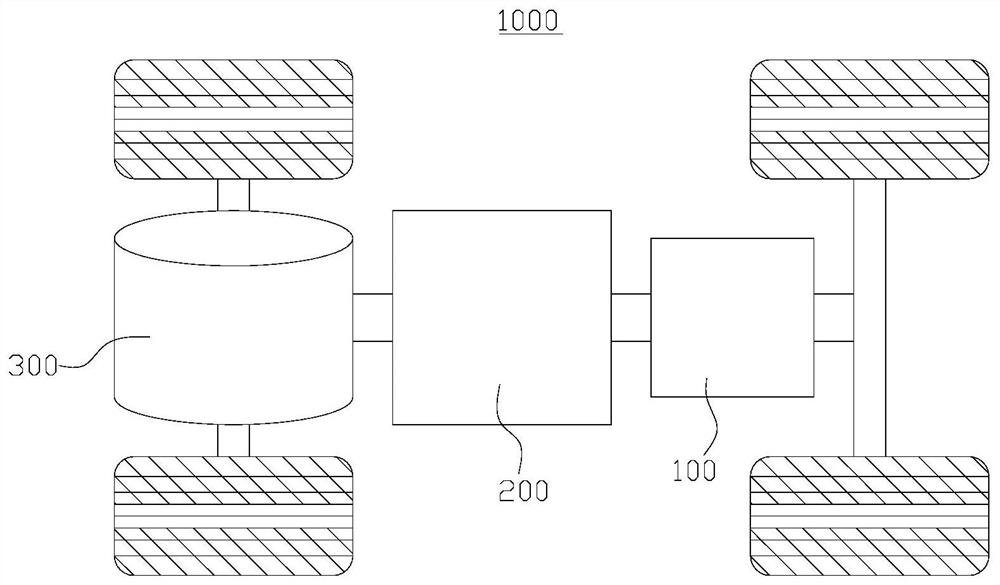
[0062] Please refer to figure 1 , figure 1 A structural diagram of the vehicle 1000 provided in this application, some embodiments. The inside of the vehicle 1000 is provided with a battery 100, and the battery 100 can be disposed at the bottom or head or tail of the vehicle 1000. The battery 100 can be used for power supply of the vehicle 1000, for example, battery 100 can act as an operating power supply of the vehicle 1000.
[0063] The vehicle 1000 may also include a controller 200 and a motor 300, and the controller 200 is used to control the battery 100 to power the motor 300, for example, for the start-up, navigation, and operation of the vehicle 1000.
[0064] In some embodiments of the present application, the battery 100 can not only be used as the operating power source of the vehicle 1000, but also supplied to the driving power source of the vehicle 1000, instead or partially replace the fuel or natural gas to drive the vehicle 1000 for the vehicle 1000.
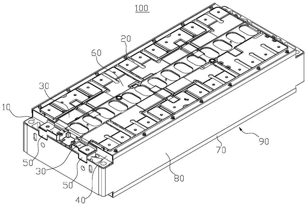
[0065] Please refer to figure 2 , figure 2 A structural diagram of the battery 100 supplied for some embodiments of the present application. The battery 100 includes a end plate 10, a battery cell 20, an output pole 30, an insulating member 40, and a mount 50.
[0066] The output pole 30 is connected to the electrode terminal of the battery cell 20 ( figure 2 Not shown), the electrical energy used to output the battery cell 20. The insulating member 40 is provided between the battery unit 20 and the end plate 10 to isolate the end plate 10 to the battery cell 20. The mount 50 is mounted on the end plate 10, and the output electrode 30 is mounted to the mount 50.
[0067] In the battery 100, the battery cell 20 can be one or more. If the battery unit 20 is plural, the plurality of battery cells 20 can be connected or paralleled or mixed, and the mixed linkage refers to both in series and in parallel. A plurality of battery cells can be directly connected in series or in parallel between the 20 hybrid or together, of course, may be a plurality of battery cells 20 in series or parallel to constitute a battery module or a hybrid, then a plurality of battery modules in series or parallel, or The mixed formation is formed.
[0068] Exemplary, in figure 2 In the middle, the battery cell 20 is a plurality of, and the plurality of battery cells 20 can be electrically connected by a bushing member 60 to achieve parallel or concatenation or mixing of the plurality of battery cells 20.
[0069] In some embodiments, please continue with reference figure 2 The end plate 10 can be two, and the plurality of battery cells 20 are between the two end plates 10, and the two end plates 10 can limit the battery cells 20.
[0070] The output pole 30 can be a metal conductor, an exemplary, an output pole 30 being a metal conductive sheet. The output electrode 30 can also be two, and an output pole 30 is electrically connected to the positive electrode terminal of a battery cell 20, and the other output electrode 30 is electrically connected to a negative electrode terminal of a battery cell 20. The two output poles 30 can be attached to the positive electrode terminal of the same battery cell 20, for example, in the case of parallel with the plurality of battery cells 20, the two output poles 30 can separately with any one of the battery. The positive electrode terminal and the negative electrode terminal of the body 20 may be electrically connected to the electrode terminal of the output pole 30 and the other output pole 30, and the negative electrode terminal of the other battery unit 20. For example, in the case where the plurality of battery cells 20 are connected in series, an output pole 30 is electrically connected to the positive electrode terminal of the battery cell 20 of the first end, and the other output pole 30 is negative in the battery cells 20 in series at the end. Electrode terminal electrical connection.
[0071] The mount 50 can also be two, and an output electrode 30 is attached to a mount 50. The two mount 50 can be mounted on both end plates 10, that is, one end plate 10, corresponding to the mount 50; figure 2 As shown, the two mount 50 can also be mounted on the same end plate 10.
[0072] The insulating member 40 can also be two, and one mount 50 is provided with an insulating member 40, and the insulating member 40 is located between the end plate 10 and the battery cells 20, and the insulating member 40 is used to insulate the battery cells 20 and the end plate 10. isolation.
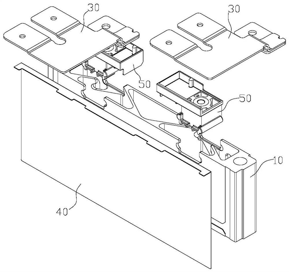
[0073] Please refer to image 3 , image 3 for figure 2 A partial exploded view of the battery 100 shown, one side of the insulating member 40 disposed in the thickness direction of the end plate 10, the mount 50 is attached to the end plate 10, the mount 50 against the insulating member 40.
[0074]The insulating member 40 is an insulating material, which can be made of rubber, plastic, etc., plastic can be PBT (polybutylene terephthalate, polyethylene terephthalate), PET (polyethyleneterephthalate, polyethylene terephthalate) ), PA (polyamide, polyamide), and the like.
[0075] Exemplary, the insulating member 40 is a plate-like structure.
[0076] In some embodiments, please continue with reference figure 2 The battery 100 can also include a bottom plate 70 and two side panels 80, a bottom plate 70, two side plates 80, and two end plates 10 to collectively define a top open space 90, and the battery cells 20 are housed in the box 90. Of course, the battery 100 can also include a cover ( figure 2 Not shown), the cover is covered with the top of the casing 90 and seals the casing 90, and the lid body coincides with the casing 90 to form a sealed space for receiving the battery cells 20.
[0077] Please refer to Figure 4 , Figure 4 for image 3 The structure shown in the mounting seat 50 is shown. In the present application embodiment, the mounting seat 50 includes a body 51, and the body 51 towards the insulating member 40 ( image 3 On the side shown), there is a guide groove 511, which is used to prevent the output pole 30 from being electrically connected between the end plate 10 through the body 51 and the insulating member 40.
[0078] The body 51 is provided with a guide groove 511 on one side of the insulating member 40, increasing the distance between the position 511 and the insulating member 40, which is not easy to form a liquid film between the insulating member 40, so that The main body 51 is less likely to form a continuous liquid film between the insulating member 40, thereby effectively reducing the liquid electrical connection between the output pole 30 and the end plate 10 through the body 51 and the insulating member 40, resulting in a mount 50 to the output pole 30 The risk of failure of insulation protection, battery 100 is not prone to short-circuit, improves the safety of battery 100.
[0079] The body 51 is made of an insulating material, and the body 51 is used to provide insulation protection for the output pole 30. The material of the body 51 can be plastic, rubber, or the like. Plastics can be PBT (polybutylene teredhalate, polyethylene terephthalate), PET (polyethylene terephthalate, polyethylene terephthalate), PA (polyamide, polyamide), and the like. Exemplary, the body 51 can be formed by thermoplastic forming.
[0080] In the present application embodiment, the arrangement of the guide groove 511 increases the distance between the position and the insulating member 40 and the insulating member 40 in order to prevent the liquid film between the position and the insulating member 40. That is, the bottom wall of the guide groove 511 to the distance of the insulating member 40 is larger than the distance between the portion of the body 51 does not provide the portion of the guide groove 511 and the insulating member 40, so that the liquid is not easy to stay in the guide groove. The bottom wall of 511 is between the insulating members 40, and the bottom wall of the guide groove 511 is less likely to form a liquid film between the insulating members 40. The deeper the depth of the flow guide 511, the larger the distance between the bottom wall of the guide groove 511 and the insulating member 40, and the lower wall of the guide groove 511 is less likely to form a liquid film between the bottom walls 40 of the guide groove 511.
[0081] In some embodiments, the depth of the guide groove 511 is greater than or equal to 2 mm so that the bottom wall of the guide groove 511 has a large distance between the insulating member 40, and the position of the guide groove 511 is provided on the body 51 is not easy. The liquid film attached to the bottom wall of the insulating member 40 and the guide groove 511 is formed such that the body 51 is less likely to form a continuous liquid film between the insulating member 40.
[0082] In some embodiments, the depth of the guide groove 511 is greater than or equal to 2.5 mm so that the distance between the bottom wall of the guide groove 511 and the insulating member 40 increases, so that the body 51 is not easily formed between the body 51 and the insulating member 40. Continuous liquid film.
[0083] In some embodiments, please continue with reference Figure 4 The body 51 has opposing first ends 512 and the second end 513 in the first direction z, and the first end 512 is used for end plate 10 ( image 3 A connection, the second end 513 is used to mount the output pole 30 ( image 3 show). The second guide groove 511 penetrates both sides on the second direction X, and the second direction X is perpendicular to the first direction Z.
[0084] Since the flow sides 511 penetrates both sides on the second direction X of the body 51, the flow of the body 51 and the insulating member 40 ( image 3 The liquid film shown is divided into two parts on both sides of the guide groove 511 on the first direction z, further reduces the body 51 and the insulating member 40 to form a continuous liquid film on the first direction z. possibility.
[0085] It should be noted that the arrangement direction of the first guide groove 511 can be the same as the second direction X, or may be set to the second direction X. in Figure 4 The arrangement direction of the first guide groove 511 is the same as the second direction X.
[0086] In some embodiments, please continue with reference Figure 4 The body 51 includes a base 514, a first abutment portion 515, and a second abutment portion 516. The base 514 has a first side surface 5141, and the first abutting portion 515 is protruded from the first side surface 5141, and the first abutting portion 515 is used to abut the insulating member 40; the second abutting portion 516 is protruded to the first side 5141 The second coupling portion 516 is configured with respect to the first abutting portion 515 on the first direction z, and the second abutting portion 516 is used to abut against the insulating member 40. The first abutment portion 515, the first side surface 5141, and the second abutment portion 516 collectively define a guide groove 511.
[0087] The first abutting portion 515 and the second abutment portion 516, which are opposite the first direction Z, can be used to abut against the insulating member 40, and improve the stability of the body 51 on the end plate 10. .
[0088] Among them, the first abutment portion 515 is closer to the first end 512 more than the second abutment portion 516.
[0089] It should be noted that a portion of the first side surface 5141 is the bottom wall of the guide groove 511.
[0090] Exemplary, the height of the first abutment portion 515 protrudes from the second side surface 5141 protrudes from the second side surface 516. This structure is easier to ensure that the body 51 is mounted on the end plate 10, the first abutting portion 515 and the second abutment portion 516 simultaneously abut the insulating member 40.
[0091] In the present embodiment, since the first abutty portion 515, the first side surface 5141, and the second abutment portion 516 collectively define the conductive fluid groove 511 such that the body 51 is on both sides of the first direction Z in the first direction. Part (the first abutment portion 515 and the second abutment 516) can be used to abut against the insulating member 40. In other embodiments, the fluid groove 511 can also penetrate to the first end 512 of the body 51, the portion of the body 51 can be used to abut against the insulating member 40; The groove 511 can also penetrate to the second end 513 of the body 51, and the portion of the body 51 can be used to abut against the insulating member 40.
[0092] In some embodiments, please continue with reference Figure 4 The body 51 is provided with a discharge hole 517 communicating with the flow guide 511, the discharge hole 517 can discharge the liquid in the guide groove 511, and it is not easy to liquid in the liquid conduit 511, further reduced the body 51 to provide a guide. The position of the groove 511 forms a liquid film between the insulating member 40.
[0093] Exemplary, the discharge hole 517 is provided in the first abutment portion 515, and the discharge hole 517 divides the first abutment portion 515 into two abutment segments 5151 spaced apart intervals in the second direction X. This structure is more advantageous to discharge liquids in the drawing groove 511.
[0094] In the present application embodiment, the body 51 may be fixed to the end plate 10, for example, the body 51 is fixed by bonding by bonding; the body 51 may be detachably connected to the end plate 10, for example, the body 51 is inserted with the end plate 10, and then the body 51 is connected to the end plate 10 by a bolt.
[0095] In some embodiments, the combination Figure 4 with Figure 5 , Figure 5 for figure 2 The mounting seat 50 of the battery 100 and the mounting of the end plate 10 is shown. The body 51 of the mount 50 is inserted with the end plate 10, and the base portion 514 of the body 51 is provided with a socchip portion 518, and a slot 11 is provided on the end plate 10, and the socket portion 518 is used to fit the socket 11. The end plate 10 is separated from the first direction Z to limit the body 51. This structure can realize the quick disassembly of the mount 50 and the end plate 10.
[0096] It should be noted that the coupling portion 518 on the base portion 514 can be one or more. in Figure 4 with Figure 5 In the case, the interposing portion 518 on the base portion 514 is two, and the two sleeve portions 518 are respectively disposed on both sides of the base portion 514 on the second direction x.
[0097] Exemplary, such as Figure 5 As shown, the slot 11 on the end plate 10 corresponds to one or one, and the tip end of the end plate 10 is provided with a downward recessed groove 12, and the groove 12 penetrates the thickness direction of the end plate 10. At both ends, slots 11 are provided on both sides of the grooves 12 opposing. Wherein, the height direction of the end plate 10 is consistent with the first direction z.
[0098] When the body 51 is mounted, the base portion 514 of the body 51 can be moved in the groove 12 in the thickness direction of the end plate 10, so that the base 514 is plugged in two insertions 518 in the second direction X, respectively. The groove 11 is attached to the end plate 10.
[0099] In some embodiments, please continue with reference Figure 4 The plug portion 518 extends along the third direction Y, and one end of the interpolation portion 518 extends beyond the first side surface 5141 for abutting with the insulating member 40. The first direction Z, the second direction X and the third direction Y are two or two vertical.
[0100] In one aspect, the interpolation portion 518 can be used to cooperate with the slot 11 on the end plate 10, to achieve a limit of the ontology 51; on the other hand, the socch-in portion 518 can also be used to abut against the insulating member 40, increase the body. 51 The contact area of the insulating member 40 further enhances the stability of the body 51 to be mounted on the end plate 10.
[0101] It should be noted that after the insertion portion 518 is inserted with the slot 11, i.e., the body 51 is mounted on the end plate 10, the first direction z is the height direction of the end plate 10, and the second direction X is the end plate. The length direction of 10, the third direction Y is the thickness direction of the end plate 10.
[0102] In some embodiments, please continue with reference Figure 4 The first abutment portion 515 has a first abutment surface 5152 for abutting with the insulating member 40. The plug portion 518 has a second abutment surface 5181 for abutting with the insulating member 40, and the second abutment surface 5181 is coplanar with the first abutment surface 5152.
[0103] The first abutment portion 515 is used to abut the first abutment surface 5152 and the interpolation portion 518 abut against the insulating member 40, which is more likely to ensure that the insulating member 40 is abutting. After the body 51 is mounted on the end plate 10, the first abutment surface 5152 and the second abutment surface 5181 simultaneously abut the insulating member 40.
[0104]Exemplary, one coupling portion 518 is coupled to one abutment section 5151, and constitutes an L-shaped structure such that the first abutting portion 515 and the two coupling portions 518 constitute a U-shaped structure, facilitating the flow groove 511 The liquid can be easier to discharge from the discharge holes 517.
[0105] In some embodiments, please continue with reference Figure 4 The mounting seat 50 may also include a screw 53 that extends one end of the screw sleeve 53 to the body 51, and the spiro 53 is used to connect to the output pole 30.
[0106] The screw 53 can be connected to the body 51 in a variety of ways, for example, a threaded hole is provided on the body 51, and the hechograph 53 is screwed within the threaded hole. This structure can realize the detachable force of the screw 53, easy to replace the screw socket 53 Further, the screw 53 is buddha in the body 51, and during the molding process of the body 51, the screw sleeve 53 is burn into the body 51, and after the body 51 is solidified, the screw jacket 53 is fixed to the body 51.
[0107] Exemplary, the spiro 53 can be a metal material such as copper, iron, aluminum, aluminum alloy, stainless steel, and the like.
[0108] Please refer to Figure 6 , Figure 6 for figure 2 The mounting seat 50 of the battery 100 and the explosion chart of the output pole 30 are shown. The spiro 53 is used to fit the screw 32 to attach the output pole 30 to the second end 513 of the body 51.
[0109] When the output pole is mounted, the screw 32 passes through the mounting hole 31 on the output pole 30 and is screwed to the screw 53, and the output electrode 30 can be mounted on the second end 513 of the body 51.
[0110] In some embodiments, please continue with reference Figure 4 The second end 513 of the body 51 is provided with a body 520, and the body 520 is distributed along the edge distribution of the second end 513 of the body 51, and the enclosure 521 for receiving portion output pole 30 is formed inside.
[0111] Exemplary, the body 520 is a rectangular distribution, and the body 520 includes a first convex portion 5201 and a second convex portion 5202, and the first convex portion 5201 and the second convex portion 5202 form a closure structure. The first convex portion 5201 protrudes over the height of the second end 513 greater than the second convex portion 5202 protrudes from the height of the second end 513. The first convex portion 5201 is located on the three edges of the rectangle, and the second convex portion 5202 is located in two sides of the rectangle, wherein a portion of the first convex portion 5201 is co-located on one side of the rectangle with a portion of the second convex portion 5202. The second abutment portion 516 is part of the first convex portion 5201.
[0112] Please refer to Figure 7 , Figure 7 for figure 2 The positional diagram of the mounting seat 50, the output pole 30, the end plate 10, and the insulator 40 of the battery 100. After the output pole 30 is mounted on the body 51, the partial portion of the output electrode 30 is located within the receiving space 521 of the outer body 520, and a portion of the first convex portion 5201 of the body 520 separates the output electrode 30 from the insulating member 40. Since the first convex portion 5201 of the outer body 520 is higher than the second convex portion 5202 ( Figure 4 It is shown that the liquid level of the liquid in the accommodating space 521 is not easily exceeded by the first convex portion 5201, and the liquid in the housing space 521 is not easy to pass through the first convex portion 5201 between the body 51 and the insulating member 40 and form a liquid film. The climbing distance between the output pole 30 and the end plate 10 is improved.
[0113] It should be noted that in the present application embodiment, the arrangement form of the guide groove 511 is not limited to the arrangement form in each of the above embodiments, and the flow groove 511 can also be in other arrangements. In some embodiments, please refer to Figure 8 , Figure 8 A structural diagram of the mount 50 provided for some embodiments of the present application. The guide groove 511 facing the insulating member 40 in the body 51 ( Figure 7 The side of the side of the side is shown such that the body 51 forms a projection 522 for contact with the insulating member 40 on one side of the insulating member 40. The guide groove 511 of this structure can also prevent the output pole 30 from being electrically connected between the end plate 10 through the body 51 and the insulating member 40, which can effectively reduce the output pole 30 and the end plate 10 through the body 51 and the insulator 40. The liquid is electrically connected to cause the mounting seat 50 to failure of the insulation protection of the output pole 30.
[0114] Among them, the shape of the projection 522 may be circular, elliptical, rectangular, and the like, the present application is not limited. Exemplary, in Figure 8 In the middle, the projection 522 is circular.
[0115] It should be noted that the features in the embodiments and embodiments in the present application may be combined with each other in the case of an unable conflict.
[0116] The above embodiments are intended to illustrate the technical solutions of the present application, and are not intended to limit the present application, and the present application can have various changes and variations for those skilled in the art. Any modification, equivalent replacement, improvement, etc. according to the spirit and principles of this application shall be included within the scope of the present application.
PUM


Description & Claims & Application Information
We can also present the details of the Description, Claims and Application information to help users get a comprehensive understanding of the technical details of the patent, such as background art, summary of invention, brief description of drawings, description of embodiments, and other original content. On the other hand, users can also determine the specific scope of protection of the technology through the list of claims; as well as understand the changes in the life cycle of the technology with the presentation of the patent timeline. Login to view more.
Similar technology patents
Trusted computing platform chip applicable to mobile communication equipment and authentication method thereof
Owner:HANGZHOU SYNOCHIP DATA SECURITY TECH CO LTD
Capacity calling method, capacity calling request device, capacity calling platform and capacity calling system
Owner:CHINA MOBILE COMM GRP CO LTD
Method, device and system for sending and receiving scheduling user data information
Owner:HUAWEI TECH CO LTD
Hidden frame glass curtain wall structure and method for mounting same
Owner:XINCHANG SICHUANG DESIGN CONSULTING CO LTD
Method and system for preventing mobile terminal from being updated to illegal firmware version
Owner:ZTE CORP
Bus chamber structure of high-voltage miniaturized air-insulated switch cabinet
Owner:吉林德蕴电气集团股份有限公司
Water-based printed circuit board (PCB) cleaning agent and preparation method thereof
InactiveCN103540460AQuick ClearanceNot easy to short circuit
Owner:合肥市华美光电科技有限公司
Classification and recommendation of technical efficacy words
- Not easy to short circuit
- improve security
Water-based printed circuit board (PCB) cleaning agent and preparation method thereof
InactiveCN103540460AQuick ClearanceNot easy to short circuit
Owner:合肥市华美光电科技有限公司
Bus chamber structure of high-voltage miniaturized air-insulated switch cabinet
Owner:吉林德蕴电气集团股份有限公司
Automatic charging system for electric automobile
Owner:WUHAN INSTITUTE OF TECHNOLOGY
Block chain system, and data storage method and apparatus
Owner:ADVANCED NEW TECH CO LTD
Pesticide micro-capsule granules and preparation method thereof
Owner:联合国南通农药剂型开发中心 +1
Method for achieving user authentication by utilizing camera
Owner:湖北微模式科技发展有限公司