Supercharge Your Innovation With Domain-Expert AI Agents!

Fan heat dissipation combination device

A combined device and fan technology, which is applied to components, mechanical equipment, machines/engines, etc. of pumping devices for elastic fluids, and can solve problems such as inability to be cleaned automatically

Inactive Publication Date: 2021-03-23
亚什兰风机无锡有限公司
View PDF0 Cites 0 Cited by
  • Summary
  • Abstract
  • Description
  • Claims
  • Application Information

AI Technical Summary

Problems solved by technology

[0006] Aiming at the deficiencies of the prior art, the present invention provides a fan heat dissipation combination device, which solves the problem that the traditional fan heat dissipation combination cannot be automatically cleaned, and at the same time provides a technical solution that can save cleaning costs

Method used


Image

  • Fan heat dissipation combination device
  • Fan heat dissipation combination device
  • Fan heat dissipation combination device

Examples


Embodiment

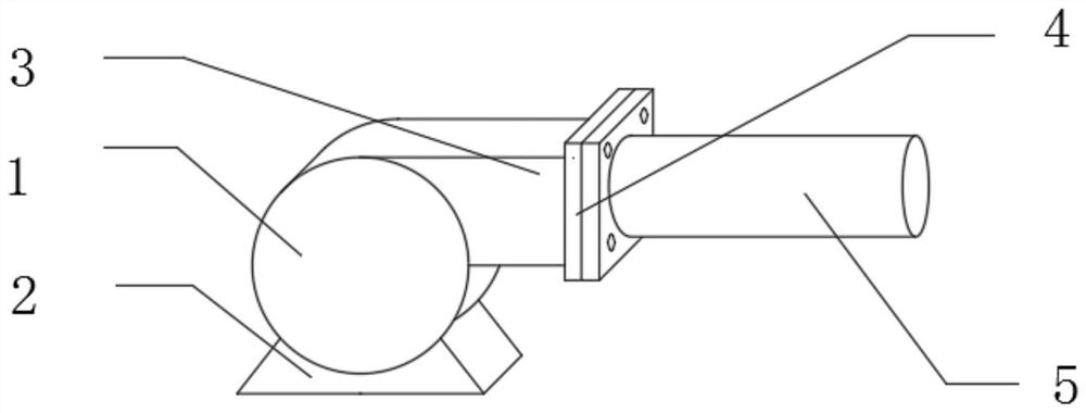
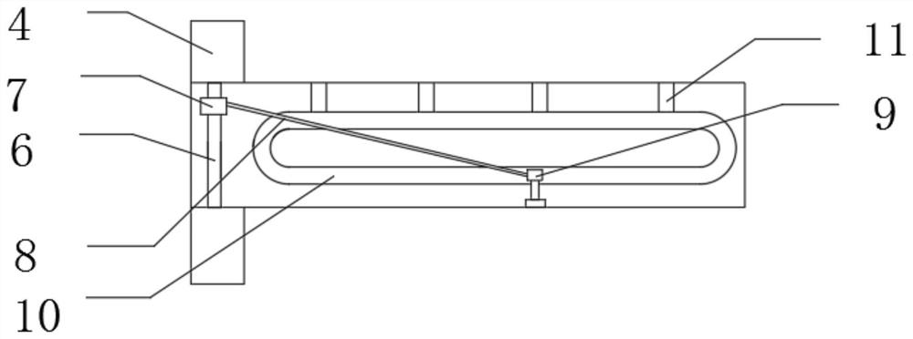
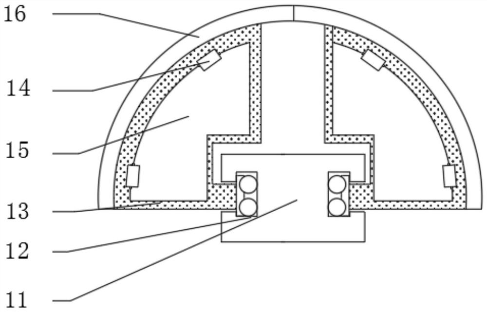
[0024] see Figure 1-3 , in this embodiment: a fan cooling combination device, including a fan main body 1, the lower end of the fan main body 1 is connected to a base 2, the upper end of the fan main body 1 is connected to an air outlet pipe 3, and one end of the air outlet pipe 3 is connected to the connection port 4 One end of the connecting port 4 is connected with an exhaust pipe 5, the inner side of the connecting port 4 is provided with a first fixed rod 6, the inner side of the first fixed rod 6 is connected with a fixed block 7, and one end of the fixed block 7 is connected with a spring rope 8, One end of spring rope 8 is connected with trolley 9, and the inboard of trolley 9 is connected with slide rail 10, and the upper end of slide rail 10 is connected with second fixed rod 11, and the inboard of slide rail 10 is provided with chute 12, and the inboard of trolley 9 The outer surface is connected with a fixed frame 13, the inner side of the one-way hinge 14 is prov...


PUM


Abstract

The invention belongs to the field of fan heat dissipation combination, and particularly relates to a fan heat dissipation combination device. The device comprises a fan body, wherein a base is connected to the lower end of the fan body, an air outlet pipe is connected to the upper end of the fan body, a connecting port is connected to one end of the air outlet pipe, an exhaust pipe is connected to one end of the connecting port, a first fixing rod is arranged on the inner side of the connecting port, a fixing block is connected to the inner side of the first fixing rod, a spring rope is connected to one end of the fixing block, a small trolley is connected to one end of the spring rope, a sliding rail is connected to the inner side of the small trolley, second fixing rods are connected tothe upper end of the sliding rail, a sliding groove is formed in the inner side of the sliding rail, a fixing frame is connected to the outer surface of the small trolley, a one-way hinge is arrangedon the inner side of the fixing frame, one end of the one-way hinge is connected with an air stopping plate, and the outer surface of the fixing frame is connected with a brush. With the fan heat dissipation combination device, the problem that a traditional fan heat dissipation combination cannot be automatically cleaned is solved, and the cleaning cost is reduced.

Description

technical field [0001] The invention relates to the field of fan heat dissipation combination, in particular to a fan heat dissipation combination device. Background technique [0002] In industrial production, many mechanical equipment will generate a lot of heat during operation, and some products that require high-temperature disinfection process, the temperature of the process disinfection workshop is also quite high, and the harm of high temperature is very harmful to the human body. Long-term high-temperature environment will dehydrate people, which can seriously endanger life. Industrial workshops generally have a large space, and even large-scale air conditioners cannot cool industrial workshops well. operating costs. Therefore, most factories need to install fan cooling devices for high-temperature workshops to discharge the high temperature in the room. It has a good cooling effect without cooling, and at the same time saves the operating cost of the factory. ...

Claims


Application Information

Patent Timeline
Patent Type & Authority Applications(China)
IPC IPC(8): F04D29/70F04D29/42B08B9/053B08B9/057
CPCB08B9/0535B08B9/057F04D29/4206F04D29/703
Inventor 蔡海滨
Owner 亚什兰风机无锡有限公司
Features
  • R&D
  • Intellectual Property
  • Life Sciences
  • Materials
  • Tech Scout
  • Unparalleled Data Quality
  • Higher Quality Content
  • 60% Fewer Hallucinations
Learn More