

A defect detection device
A defect detection and equipment technology, applied in the direction of optical defect/defect, measuring device, instrument, etc., can solve the problems of inconvenient, manual blanking of defective products, etc., and achieve the effect of easy movement and fixation
- Summary
- Abstract
- Description
- Claims
- Application Information
AI Technical Summary
Problems solved by technology
Method used
Image


Examples
Embodiment 1
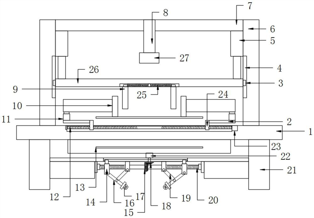
[0020] see Figure 1-4 , a defect detection device, comprising a base 1, a side support rod 6, a top plate 7, a bottom support rod 21 and a detection structure, the upper side of the base 1 is fixed with a side support rod 6, and the side support rod 6 A top plate 7 is fixed at the end, a detection structure is provided on the base 1, a bottom support rod 21 is fixed on the lower side of the base 1, and a moving structure is provided on the side of the bottom support rod 21, and the detection structure includes a transmission structure, horizontal clamping structure, vertical clamping structure and top visual structure, the base 1 is set in the middle of the transmission structure, the base 1 is provided with a horizontal clamping structure and the horizontal line clamping structure is set at At both ends of the transmission structure, a longitudinal clamping structure is arranged under the side of the top plate 7 , and a top visual structure is arranged under the top plate 7 ...
Embodiment 2
[0027] Compared with Embodiment 1, the improvement of this embodiment lies in that: the bottom support rod 21 is provided with an anti-slip pad. Use the non-slip pad to fix the device to avoid deviation during work.
[0028] The working principle of the present invention is: first place the raw material on the transmission structure, use the driving motor 29 to drive the driving shaft 28, so that the driving roller 31 rotates, drive the transmission belt 13 to drive the detection raw material to move laterally, and transmit it to the visual camera through the transmission structure 27 below to detect, first use the hydraulic cylinder 5 to elongate, so that the top pressing plate 9 moves longitudinally, so that the top pressing plate 9 is located inside the side pressing plate 10, and then the side motor 23 drives the side screw rod 23, so The side screw 23 is rotated, and the clamping and fixing sleeve 24 is slidably connected with the base 1, so that the clamping and fixing s...
PUM
 Abstract
Description
Claims
Application Information