Power cabinet

A technology for power cabinets and cabinets, applied in the field of electric power, can solve problems such as troublesome opening or closing of cabinet doors, looseness, inconvenience in use, etc., and achieve the effects of simple internal structure, reliable locking performance, and simple operation.

Active Publication Date: 2021-03-30
XIAJIN POWER SUPPLY CO STATE GRID SHANDONG ELECTRIC POWER CO
View PDF5 Cites 0 Cited by
  • Summary
  • Abstract
  • Description
  • Claims
  • Application Information

AI Technical Summary

Problems solved by technology

[0002] The power cabinet, also known as the control cabinet, is a closed or semi-closed metal cabinet that assembles components such as switchgear, measuring instruments, protective appliances and auxiliary equipment in accordance with the requirements of electrical wiring. The layout should meet the requirements of the normal operation of the power system and facilitate maintenance. Therefore, cabinet locks are often installed on the cabinet door to realize the opening and clos

Method used


Image

  • Power cabinet
  • Power cabinet
  • Power cabinet

Examples


Example Embodiment

[0027] The preferred embodiments of the present invention will be described in detail below with reference to the accompanying drawings to be more readily understood by those skilled in the art, so as will be more clearly defined by those skilled in the art.

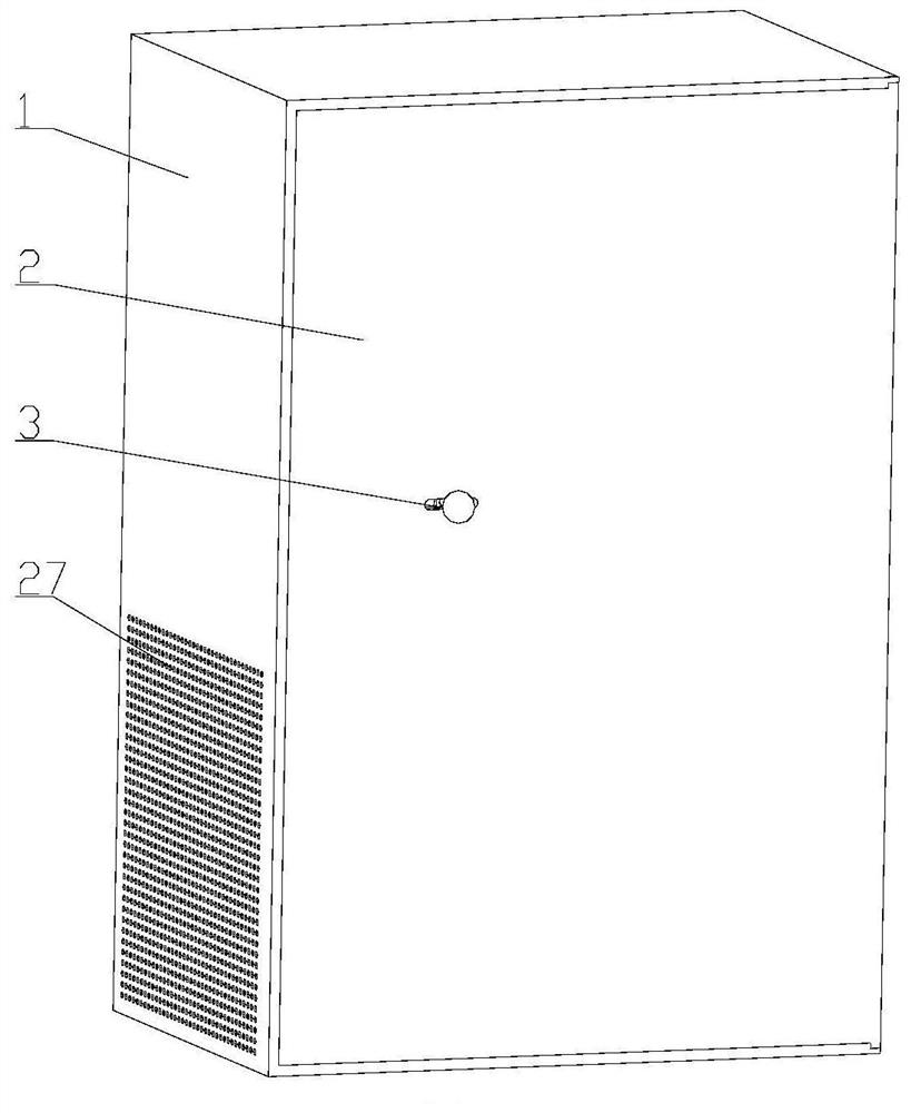
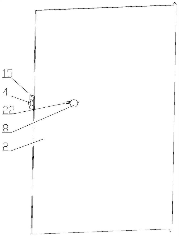
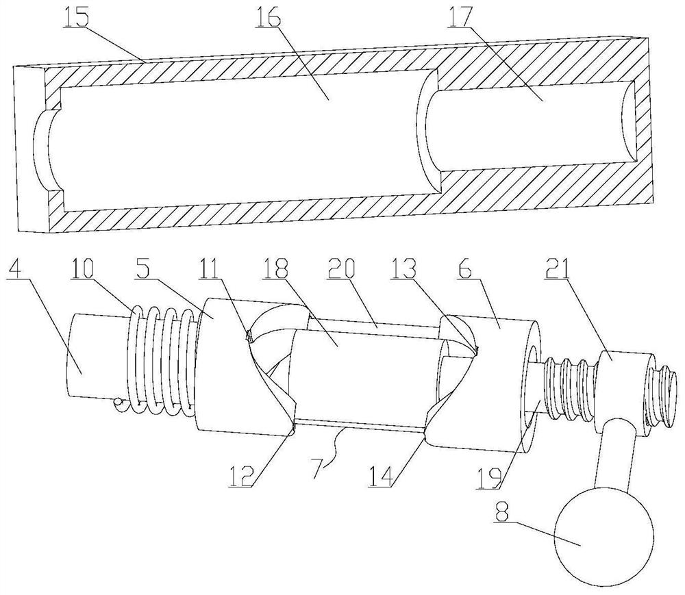
[0028] See Figures 1 to 10 As shown, the power cabinet of the present embodiment includes a cabinet 1, the cabinet door 2 and the cabinet lock 3, the cabinet door 2 is hinged, the cabinet lock 3 is disposed on the cabinet door 2 and can be equipped with the cabinet 1, cabinet The lock 3 includes a lock rod 4, a movable lock 5, a fixed lock seat 6, a lock core 7, and a housing 8, and the lock rod 4 is used to fit the cabinet 1, and the inner wall of the cabinet 1 is provided with a lock groove 9. The lock groove 9 does not penetrate, and the lock rod 4 achieves the insertion fitting of the cabinet body 1 by the insertion fit of the lock groove 9, and the locking rod 4 is connected to the reset spring 10, and the active lock 5...


PUM


Abstract

A power cabinet disclosed by the present invention comprises a cabinet body, a cabinet door and a cabinet lock, the cabinet lock is arranged on the cabinet door and comprises a lock rod, a movable lock base, a fixed lock base, a lock cylinder and an operation rod, and the lock rod is used for the plugging cooperation with the cabinet body and is sleeved with a reset spring. The end, away from thefixed lock base, of the movable lock base is connected with the lock rod and is used for driving the lock rod to move horizontally left and right. A first clamping groove and a second clamping grooveare formed in the end, close to the fixed lock base, of the movable lock base, the vertical projection of the first clamping groove falls at the left side of the vertical projection of the second clamping groove, and a third clamping groove and a fourth clamping groove are formed in the end, close to the movable lock base, of the fixed lock base. The third clamping groove corresponds to the firstclamping groove, the fourth clamping groove corresponds to the second clamping groove, and the vertical projection of the third clamping groove falls at the right side of vertical projection of the fourth clamping groove. When the lock cylinder is connected with the first clamping groove and the third clamping groove in a matched manner, the lock rod is separated from the cabinet body, and when the lock cylinder is connected with the second clamping groove and the fourth clamping groove in a matched manner, the lock rod is matched with the cabinet body in an inserted manner, so that operationis easy, and the internal structure is simple; moreover, the clamping groove has a self-locking function, so that the firm locking performance of a mechanical lock is completely met.

Description

technical field [0001] The invention relates to the field of electric power, in particular to an electric power cabinet. Background technique [0002] The power cabinet, also known as the control cabinet, is a closed or semi-closed metal cabinet that assembles components such as switchgear, measuring instruments, protective appliances and auxiliary equipment in accordance with the requirements of electrical wiring. The layout should meet the requirements of the normal operation of the power system and facilitate maintenance. Therefore, cabinet locks are often installed on the cabinet door to realize the opening and closing of the cabinet door and the cabinet body. However, during long-term use, the connection between the cabinet door and the cabinet body of the power cabinet will inevitably become loose. As a result, conventional cabinet locks cannot meet the requirements, and mechanical locks are required. The structure of mechanical locks is relatively complicated. On the ...

Claims


Application Information

Patent Timeline
IPC IPC(8): H02B1/38E05B65/52E05B15/00
CPCH02B1/38E05B65/523E05B15/0053E05B15/00
Inventor 卜勇徐婷婷
Owner XIAJIN POWER SUPPLY CO STATE GRID SHANDONG ELECTRIC POWER CO
Why Eureka
Try Eureka