Spiral fiber bragg grating, preparation method and all-fiber orbital angular momentum light beam generator
A technology of orbital angular momentum and fiber grating, applied in the direction of grating fiber, cladding fiber, optical waveguide light guide, etc., can solve the problems of insufficient resonance peak depth, uncontrollable grating resonance wavelength and resonance peak depth, low efficiency, etc., to achieve Deep resonance peak, good protection effect and low insertion loss
- Summary
- Abstract
- Description
- Claims
- Application Information
AI Technical Summary
Problems solved by technology
Method used
Image

Examples
Example Embodiment
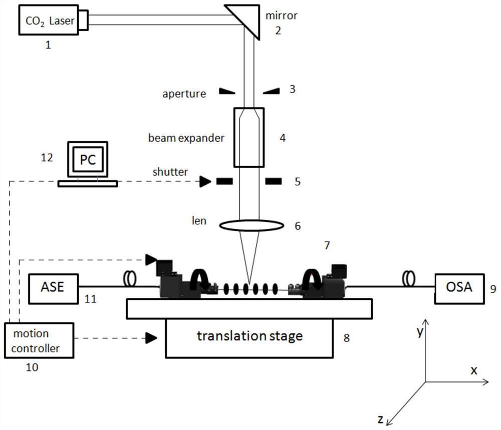
[0036] A method for preparing a spiral fiber grating 30 provided in a specific embodiment of the present application includes the following steps:
[0037] Step S1: prepare the optical fiber, and strip the coating layer from the optical fiber;
[0038] Step S2: fixing the optical fiber on the fixture of the mobile platform;
[0039] Step S3: CO 2 The laser beam is focused on the cladding 20 of the optical fiber; while the optical fiber is rotated around its own axis, it is also translated in the horizontal direction, CO 2 The laser beam performs helical refractive index modulation on the fiber cladding 20 and forms a helical refractive index variation modulated long-period fiber grating on the cladding 20 .
[0040] In the above step S3, through the debugging of the optical path, the low-energy CO 2 The laser beam is focused on the fiber cladding 20 . Then ensure that the optical fiber rotates while also performing horizontal translation. Therefore, the present application e...
Example Embodiment
[0073] Embodiment two
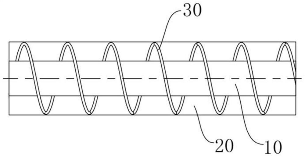
[0074] The present application also provides a spiral fiber grating 30 . It is a modulated fiber grating with a helical refractive index change formed on the fiber cladding 20
[0075] The present application also provides a spiral fiber grating 30, which is prepared by the above-mentioned preparation method.
[0076] Preferably, through the preparation method of Embodiment 1, a modulated long-period fiber grating with a helical refractive index change can be formed on the few-mode fiber cladding 20, and the grating is a helical long-period fiber grating based on a few-mode fiber.
[0077] Applications use graded or stepped-index few-mode fibers that support stable propagation of higher-order modes alone. Through the method of modulating the helical refractive index in the few-mode fiber cladding 20, under the condition of phase matching, the fundamental mode is coupled to a specific high-order mode by the few-mode helical fiber grating, which is exci...
Example Embodiment
[0078] Embodiment Three
[0079] The application also provides an all-fiber orbital angular momentum beam generator, figure 2 It is a structural schematic diagram of an orbital angular momentum beam generator according to an embodiment of the present invention.
[0080] In the specific embodiment of the application, the orbital angular momentum beam generator is made by using a few-mode fiber, and the few-mode fiber includes a core 10 and a cladding 20 . A spiral fiber grating 30 is formed on the few-mode fiber cladding 20 . The spiral fiber grating here is specifically a spiral long-period fiber grating, which is a spiral long-period fiber grating based on a few-mode fiber.
[0081] The helical long-period fiber grating is prepared by the preparation method of the first embodiment above.
[0082] Few-mode fiber is a graded or jump-index fiber that supports independent and stable propagation of higher-order modes.
[0083] The orbital angular momentum beam generator of th...
PUM
| Property | Measurement | Unit |
|---|---|---|
| Cycle | aaaaa | aaaaa |
Abstract
Description
Claims
Application Information
 - R&D Engineer
- R&D Manager
- IP Professional
- Industry Leading Data Capabilities
- Powerful AI technology
- Patent DNA Extraction
Browse by: Latest US Patents, China's latest patents, Technical Efficacy Thesaurus, Application Domain, Technology Topic.
© 2024 PatSnap. All rights reserved.Legal|Privacy policy|Modern Slavery Act Transparency Statement|Sitemap