Poppet valve device for improving RTO sealing performance
A lift valve, sealing technology, applied in the direction of valve device, valve heating/cooling device, lift valve, etc., can solve the problems of complex exhaust gas composition, reduce the service life of the device, increase the leakage rate, etc., to improve the sealing performance of RTO , Improve the cooling effect and promote the effect of cold and heat exchange
- Summary
- Abstract
- Description
- Claims
- Application Information
AI Technical Summary
Problems solved by technology
Method used
Image
Examples
Embodiment 1
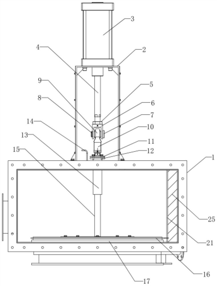
[0036] Embodiment 1: In use, the cylinder 3 can control the movement of the push rod 4, and the push rod 4 drives the valve plate 16 to move through the guide cylinder 13 and the valve rod 15. When the valve plate 16 is covered on the valve seat 17, the poppet valve is in the position of Closed state; when the valve plate 16 is far away from the valve seat 17, the poppet valve is in the open state, at this time, exhaust gas can be provided to the combustion chamber, and the operation is flexible.
Embodiment 2
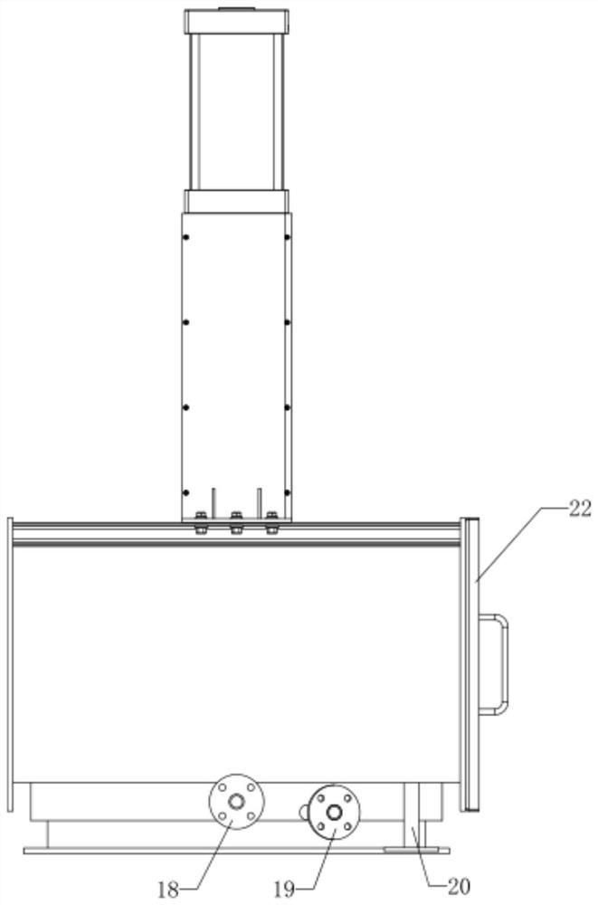
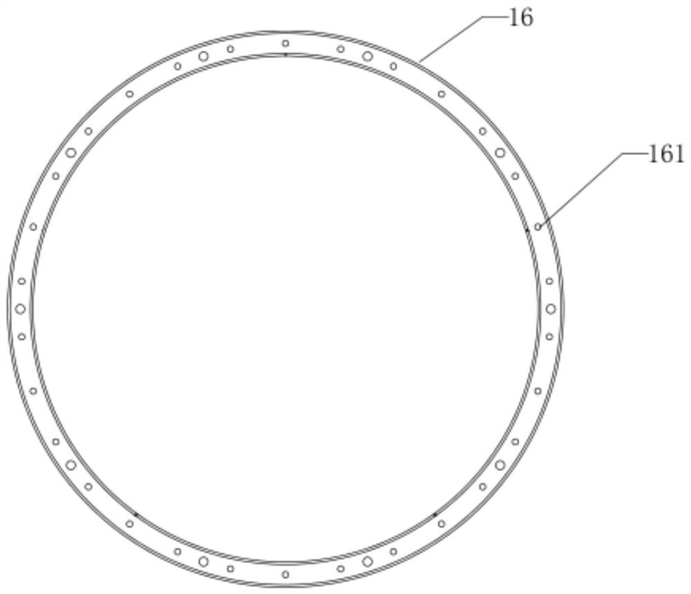
[0037] Embodiment 2: This device has a triple sealing function. First, the valve plate 16 can be attached to the valve seat 17, which is a "hard seal"; secondly, when the valve plate 16 is attached to the valve seat 17, the valve plate 16 There is a valve plate groove 161 on the top, so a sealed chamber is formed between the valve plate groove 161 and the valve seat 17. At this time, compressed air is introduced through the compressed air inlet 18 of the air chamber, so that a suppressed environment is formed in the above-mentioned sealed chamber. , the compressed air will be emitted to the outside of the chamber, so the exhaust gas cannot go out from this chamber, thereby achieving "air tightness"; finally, compressed air can also be introduced into the bent tube 14, where the compressed air is located in the graphite packing 12 is in contact with the guide cylinder 13 to prevent the exhaust gas from dissipating to the outside through the gap, thereby realizing the "shaft seal...
Embodiment 3
[0038] Embodiment 3: During the movement of the valve plate 16, whenever the valve plate 16 drives the infrared receiver 23 to pass the infrared transmitter 24 in the guide plate 21, the infrared receiver 23 will count and feed back this information to the PLC The controller 48 and the PLC controller 48 will control the drive motor 38 to run at high power according to the receiving frequency, and the drive motor 38 will drive the transmission shaft 39 to rotate when the valve plate 16 moves more times and the frequency is higher, so that the cam 40 and the driving wheel 41 rotate synchronously. On the one hand, the cam 40 is arranged under the push plate 36. During the continuous rotation, the cam 40 will intermittently lift up the push plate 36. When the push plate 36 is lifted up, , the movable plate 34 will be moved up through the extension rod 35, and then the cold air in the connecting pipe 29 will be squeezed into the cold air chamber 28, and the cold air chamber 28 will ...
PUM
 Abstract
Description
Claims
Application Information
 - R&D Engineer
- R&D Manager
- IP Professional
- Industry Leading Data Capabilities
- Powerful AI technology
- Patent DNA Extraction
Browse by: Latest US Patents, China's latest patents, Technical Efficacy Thesaurus, Application Domain, Technology Topic, Popular Technical Reports.
© 2024 PatSnap. All rights reserved.Legal|Privacy policy|Modern Slavery Act Transparency Statement|Sitemap|About US| Contact US: help@patsnap.com


